 Draw
Guide
Draw
Guide
Draw
Guide
Chapter
4
Changing Object Attributes
This document is Copyright © 2005–2011 by its contributors as listed below. You may distribute it and/or modify it under the terms of either the GNU General Public License (http://www.gnu.org/licenses/gpl.html), version 3 or later, or the Creative Commons Attribution License (http://creativecommons.org/licenses/by/3.0/), version 3.0 or later.
All trademarks within this guide belong to their legitimate owners.
Contributors
John Cleland Martin Fox Jean Hollis Weber
Feedback
Please direct any comments or suggestions about this document to: documentation@global.libreoffice.org
Acknowledgments
This chapter is based on an original French document written for OpenOffice.org 1.x by Michel Pinquier (translated into English by Alex Thurgood) and previous content revised by Jim Taylor. The chapter was revised for OpenOffice.org 2.0 by Linda Worthington, Daniel Carrera, Jean Hollis Weber, and Agnes Belzunce, and later translated into German by Wolfgang Uhlig. The German revisions were then translated into English and revised for OpenOffice.org 3.3 and LibreOffice 3.3 by Martin Fox. Other contributors included Peter Hillier-Brook, Hazel Russman, Gary Schnabl, and Claire Wood.
Publication date and software version
Published 3 July 2011. Based on LibreOffice 3.3.3.
Some keystrokes and menu items are different on a Mac from those used in Windows and Linux. The table below gives some common substitutions for the instructions in this chapter. For a more detailed list, see the application Help.
|
Windows/Linux |
Mac equivalent |
Effect |
|
Tools > Options menu selection |
LibreOffice > Preferences |
Access setup options |
|
Right-click |
Control+click |
Open context menu |
|
Ctrl (Control) |
z (Command) |
Used with other keys |
|
F5 |
Shift+z+F5 |
Open the Navigator |
|
F11 |
z+T |
Open Styles and Formatting window |
Contents
Customizing line and arrow styles 8
Editing the inside (fill) of an object 11
Creating your own fill color 13
Creating your own hatching (line pattern) 15
Creating your own bitmap fill 16
To change an object’s attributes (such as color or border width) you can use the Line and Filling toolbar, the Text Formatting toolbar, or the context menu.
If
the Line and Filling toolbar is not visible, you can display it using
View
> Toolbars > Line and Filling.
From here you can edit the most common object attributes. You can
also open the Line dialog by clicking on the Line
![]() icon and the Area dialog by clicking on the Area
icon and the Area dialog by clicking on the Area
![]() icon to see more options.
icon to see more options.
|
|
||
|
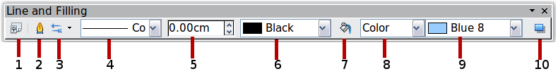
1 Styles and Formatting 2 Line 3 Arrow Style |
4 Line Style 5 Line Width 6 Line Color |
7 Area 8–9 Area Style / Filling 10 Shadow |
|
Figure 1: Line and Filling toolbar |
||
When you select text, the Line and Filling toolbar changes to show text formatting options. You can also display the Text Formatting toolbar by choosing View > Toolbars > Text Formatting.
|
|
|
Figure 2: Text Formatting toolbar (when text is selected) |
When an object is selected, you can right-click on the object to open a context menu (Figure 3). The context menu provides additional access to the options shown above and another way to change an object’s attributes. The entries with a small arrow on the right-hand side contain a submenu.
Lines, arrows, and the borders of an object are managed through the same dialog (Figure 5).
You can change some properties from the Line and Filling toolbar. To see more options, select the object and right-click on the object and choose Line from the context menu. This opens the Line dialog.
In most cases the property you want to change is the line’s style (solid, dashed, invisible, and so on), its color, or its width. These options are all available from the Line and Filling toolbar.
You can also edit these properties from the Line dialog. They are on the first tab, left column (see Figure 5). From the Line dialog you can also change the line’s transparency. Figure 7 illustrates different degrees of transparency.
Arrowheads
(and other line endings—usually
referred to in this guide collectively as arrows) are a line
property. Select a line and click on the Arrow
Style
![]() icon. This opens the Arrowheads menu.
icon. This opens the Arrowheads menu.
There are several types of arrowheads available. Each end of the line can have a different arrowhead (or no arrowhead).
|
Note |
Arrowheads are only applicable to lines. They have no effect on the border of an object. |
In the Line dialog (Figure 5), Arrow styles on the right-hand side contains a number of options to fine tune the arrow properties. If Synchronize ends is selected, both line endings will have the same appearance. The Center option places the center of the arrow over the end point of the line. If this option is not selected, the line ends at the far edge of the arrow. The following sketch illustrates the difference.
Lines can have a shadow property associated with them.
Check
the box Use shadow to enable this feature. The properties
shown—position, distance, color, and transparency—may be
independently adjusted to your choice and the results seen in the
preview window. You can also click on the Filling
![]() icon on the Line
and Filling toolbar—next
to the area fill functions – to get a basic shadow.
icon on the Line
and Filling toolbar—next
to the area fill functions – to get a basic shadow.
Customizing line and arrow styles
You are not constrained to using the line and arrow styles provided by default in Draw. You can modify the styles and create your own.
In the Line dialog, click on the Line Styles tab (see Figure 11). From here you can customize the line styles or create your own by clicking on the Add button. You can change the length of the dashes, the space between them, and several other attributes.
Use
the Load
Line Style
![]() and
Save
Line Style
and
Save
Line Style
![]() icons to save a new definition or read one from disk (file extension
.sod).
icons to save a new definition or read one from disk (file extension
.sod).
You can also create your own arrowheads to provide some interesting effects, such as:
The first step is to draw a curve with the shape you want for the arrowhead.
|
Note |
The
arrowhead must be a curve. A curve is something you could draw
without lifting a pencil. For example,
|
Select the curve, open the Line dialog, and go to the Arrow Styles page. Click on Add, enter a name for the arrow style and click OK (see Figure 13).
|
Tip |
The part of the shape which should point in the direction of the line must be drawn facing upwards. In Figure 12 the top of the shape will point towards the “outside” of the line. |
Now you can access the new style from the Arrow style list (Figure 14) or the Arrowheads dialog (Figure 8).
Editing the inside (fill) of an object
The LibreOffice term for the inside of an object is Area fill. The area fill of an object can be a uniform color, a gradient, a hatching pattern, or an image. It can be made partly or wholly transparent and can throw a shadow.
In most cases, you will choose one of the standard fill options, whether it is a color, a gradient or an image. These options are all available from the Line and Filling toolbar.
If you want no fill at all, select the object you wish to edit and on the Line and Filling toolbar select the option Invisible on the pull down list at the right of the paint can.
Select the object you wish to edit. On the Line and Filling toolbar, select Color on the pull down list at the right of the paint can, and then choose a color from the right-hand menu.
Select the object you wish to edit. On the Line and Filling toolbar, select Gradient and then choose a gradient from the right-hand menu.
The OOo term for line patterns is Hatching. Select the object you wish to edit. On the Line and Filling toolbar, select Hatching and then choose an option from the menu.
You can fill an object with a bitmap image (as opposed to a vector graphic image). Select the object you wish to edit. On the Line and Filling toolbar, select Bitmap and then choose an option from the menu.
Click on the Filling
![]() icon on the Line
and Filling toolbar—next
to the area fill functions (Figure 21).
icon on the Line
and Filling toolbar—next
to the area fill functions (Figure 21).
Click
on the Area
icon
![]() to bring up the Area dialog. From this dialog, you can fine tune the
area fill of an object in greater detail.
to bring up the Area dialog. From this dialog, you can fine tune the
area fill of an object in greater detail.
Click on the Colors tab of the Area dialog (Figure 22). From here you can modify existing colors or create your own.
Depending on the color model in use (RGB or CMYK can be selected from the pull down menu), you can change the individual values of the constituent colors—Red, Green, and Blue or Cyan, Magenta, Yellow, and Black. Click on Add to add this color to the color table. Clicking on the Modify button will change the values of the current color (here it is Blue 8, shown in the upper rectangle) to those on the screen in the lower rectangle. The Edit button allows you to fine tune the color using a palette with visual feedback.
Further explanation about color palettes can be found in Chapter 8, Tips and Tricks.
On the Area dialog, click on the Gradients tab. From here you can modify existing gradients or create your own.
A gradient works by creating a smooth transition from one color to another. First, you need to choose two colors (Figure 24).
Then choose a type of gradient. There are several available (Linear, Axial, Radial, and so on) and each has up to four different options to specify it in detail. For example, a radial gradient has a center you can specify (Figure 25).
Figure 26 shows how an ellipsoid gradient is rotated, moved vertically and horizontally, and the color of the border area varied.
Creating your own hatching (line pattern)
On the Area dialog, click on the Hatching tab (Figure 27). From here you can modify existing hatchings (line patterns) or create your own.
You can customize options like the spacing between lines, the angle and the color of the lines. There is no way to edit the line thickness.
You can add your own bitmap images to fill an area. First, you need to create the bitmap image. This could be a photo or another sketch you have created in another program. For example, you can draw something with Draw and export it as a PNG format image file.
To export a PNG image file: Create the image, select it, then choose File > Export, choose PNG from the pull-down list of file formats, give the file a name, and save it.
To use an image as a bitmap fill, open the Area dialog and click on the Bitmaps tab (Figure 28).
From there you can add new bitmap images to serve as area fills. Click on Import and choose a file you previously saved. Give it a name that will make it easy to remember. The last imported image will appear at the bottom of the pull-down list of bitmap fills. Now you can use that image as an area fill.
|
Tip |
If the imported image seems to be very small in the preview (Figure 27) you probably forgot to select the image before you exported it. In that case, the exported image would be the whole page with a (small) drawing on it. |
First, select the object you want to apply a custom shadow to. Open the Area dialog and go to the Shadow tab (Figure 28). There you can customize the shadow’s position, distance and color.
Shadows can also have transparency, so the shadow does not hide objects behind it.
You can make objects partly or fully transparent, or even a with a varying degree of transparency (as a gradient). On the Transparency page (Figure 32), choose Transparency (for a uniform transparency) or Gradient for a gradient transparency.
An example of gradient transparency is shown in Figure 33. See also “Dynamic gradients” on page 23.
Suppose that you want to apply the same area fill, line thickness, and border to a set of objects. This repetitive process can be greatly simplified by the use of styles. Styles allow you to define a formatting template (a style) and then to apply that style to multiple objects. For more about styles, see Chapter 6, Introduction to Styles, in the Writer Guide.
Click
on the Styles
and Formatting
![]() icon on the Line
and Filling toolbar or press the F11
key to open the Styles and Formatting window (Figure 34). This window
can be docked to the left or right side of the main Draw window, if
you wish.
icon on the Line
and Filling toolbar or press the F11
key to open the Styles and Formatting window (Figure 34). This window
can be docked to the left or right side of the main Draw window, if
you wish.
Select
an object and customize the area fill and border. When you are
satisfied, click on the New
Style from Selection
![]() icon on the Styles and Formatting window. This defines a new style
based on the selected object. Type a name for the new style and click
OK.
icon on the Styles and Formatting window. This defines a new style
based on the selected object. Type a name for the new style and click
OK.
Once the new style is defined, you can apply it to other objects. Select another object and double-click on the style name you defined. The new object will acquire the area fill and line properties of that style.
|
Tip |
Question: What happens if I modify a style after it has been applied? Answer: Then every object with that style is updated automatically! |
Modifying
a style is similar to creating a new style. Select an object with
that style and change the area and line properties.
When satisfied, click on the Update
Style icon
![]() .
Alternatively click the Styles and Formatting icon or press
F11, right-click the style you wish to modify and select
Modify. Edit the properties you want to change and click OK to
finish.
.
Alternatively click the Styles and Formatting icon or press
F11, right-click the style you wish to modify and select
Modify. Edit the properties you want to change and click OK to
finish.
First make sure that the Drawing
toolbar is selected (View
> Toolbars > Drawing). On the Drawing
toolbar, locate the Effects
icon
![]() .
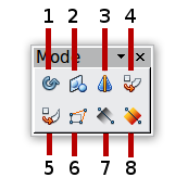
Click on the arrow
next to that icon. This opens the Mode toolbar with all the special
effect tools (see Figure 35).
.
Click on the arrow
next to that icon. This opens the Mode toolbar with all the special
effect tools (see Figure 35).
|
|
|
|
|
1 Rotate 2 Flip 3 In 3D Rotation Object |
4 Set in Circle (perspective) 5 Set to Circle (slant) 6 Distort |
7 Transparency 8 Gradient |
|
Figure 35: Mode tear-off submenu |
||
The tools are described in the following sections with the exception of the 3D rotation tool, which is described in Chapter 7, Working with 3D Objects.
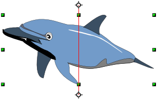
Click on the Effects
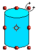
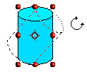
![]() icon to select the Rotate
tool. Then select an object. The selected object will have red
handles instead of the usual green handles.
icon to select the Rotate
tool. Then select an object. The selected object will have red
handles instead of the usual green handles.
|
|
Grab one of the handles and move it to rotate the object. The black circle in the middle of the object is the pivot (center of rotation). You can move the location of the pivot with the mouse. |
|
Select
an object and click on the Flip
icon
![]() .
You will see a dashed line through the middle of the object.
.
You will see a dashed line through the middle of the object.
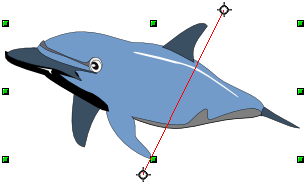
This
dashed line is the axis
of symmetry. The object will be reflected about
this line. Move one or both ends of the line with your mouse to set
the orientation of the axis.
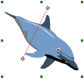
Then,
grab any one of the eight green handles and move it across to the
other side of the dashed line. The new position of the figure is
shown faintly until the mouse is released.
|
Note |
If you press the Shift key while moving the line, the line will rotate in 45-degree increments. |
Officially, this useful command does not (yet) exist in Draw. It can, however, be easily emulated.
Move the axis of symmetry to the desired location of the mirror axis. Copy the object to the clipboard. Flip the object, then click on an empty area of the Draw screen in order to deselect the object. Paste from the clipboard to put a copy of the object in its original location and now you have a mirror copy.
There are three tools on the Effects menu that let you drag the corners and edges of an object to distort the image.
The Distort tool distorts an object in perspective, the Set to Circle (slant) and Set in Circle (perspective) tools both create a pseudo three-dimensional effect.
The results of using these tools are shown in the following figures.
Select
an object and click on the Distort
icon
![]() .
Draw will ask if you want to transform the object to a curve. This is
a necessary step before distortion, so click Yes.
Then you can move the object handles to stretch it.
.
Draw will ask if you want to transform the object to a curve. This is
a necessary step before distortion, so click Yes.
Then you can move the object handles to stretch it.
The corner handles distort, as shown in Figure 37. The midpoint handles distort the figure either horizontally (handle on vertical side of figure) or vertically (handle on horizontal side of figure).
Select
an object and click on the Set
in Circle (perspective)
![]() icon. Draw will ask if you want to transform the object to a curve.
This is a necessary step before distortion, so click Yes.
Then you can move the object handles to give a pseudo
three-dimensional perspective).
icon. Draw will ask if you want to transform the object to a curve.
This is a necessary step before distortion, so click Yes.
Then you can move the object handles to give a pseudo
three-dimensional perspective).
Select an object and click on
the Set
to Circle (slant)
![]() icon. Draw will ask if you want to transform the object to a curve.
This is a necessary step before distortion, so click Yes.
Then you can move the object handles to give a pseudo
three-dimensional slant perspective.
icon. Draw will ask if you want to transform the object to a curve.
This is a necessary step before distortion, so click Yes.
Then you can move the object handles to give a pseudo
three-dimensional slant perspective.
|
Note |
Transforming an object into a curve is a safe operation, but it cannot be reversed other than by clicking the Undo button. |
You can control transparency gradients in the same manner as color gradients. Both types of gradient can be used together. With a transparency gradient, the direction and degree of an object’s fill color changes from opaque to transparent (in a regular gradient, the fill changes from one color to another, but the degree of transparency remains the same).
If
you have assigned transparency to an object with a color fill, you
can control the transparency by clicking on the Transparency
icon
![]() .
To define a transparent gradient, select an object, choose a
transparency fill from the Line
and Filling toolbar, The transparency icon is now
active. When you click on this icon, a dashed line connecting two
squares appears on the object. Move the two squares to modify the
gradient. You can define the direction of the gradient (vertical,
horizontal, or at any angle) and the spot at which the transparency
begins.
.
To define a transparent gradient, select an object, choose a
transparency fill from the Line
and Filling toolbar, The transparency icon is now
active. When you click on this icon, a dashed line connecting two
squares appears on the object. Move the two squares to modify the
gradient. You can define the direction of the gradient (vertical,
horizontal, or at any angle) and the spot at which the transparency
begins.
A
regular color gradient can be defined in the same manner. Select an
object, choose a gradient fill from the Line
and Filling toolbar. The Gradient
icon
![]() is now active. When you click on the gradient icon, a dashed line
connecting two squares appears on the object, just as it does for a
transparency gradient.
is now active. When you click on the gradient icon, a dashed line
connecting two squares appears on the object, just as it does for a
transparency gradient.
In both cases, click outside the object to set the gradient.
|
Note |
If the transparency and gradient icons are not visible, you can display them using View > Toolbars > Mode. Moving the squares will have different effects, depending on the type of gradient. For example, for a linear gradient, the start and end squares of the gradient will always be situated to either side of the center point of the object. |
The three examples in Figure 40 demonstrate how the type and degree of transparency can be controlled.
 is a curve but
 is not a curve. You can however
draw forms which are not curves and then at the end convert them
to a curve.
is not a curve. You can however
draw forms which are not curves and then at the end convert them
to a curve.