 Draw
Guide
Draw
Guide
Draw
Guide
Chapter
2
Drawing Basic Shapes
This document is Copyright © 2005–2011 by its contributors as listed below. You may distribute it and/or modify it under the terms of either the GNU General Public License (http://www.gnu.org/licenses/gpl.html), version 3 or later, or the Creative Commons Attribution License (http://creativecommons.org/licenses/by/3.0/), version 3.0 or later.
All trademarks within this guide belong to their legitimate owners.
Contributors
John Cleland Martin Fox Jean Hollis Weber
Feedback
Please direct any comments or suggestions about this document to: documentation@global.libreoffice.org
Acknowledgments
This chapter is based on an original French document written for OpenOffice.org 1.x by Michel Pinquier (translated into English by Alex Thurgood) and previous content revised by Jim Taylor. The chapter was revised for OpenOffice.org 2.0 by Linda Worthington, Daniel Carrera, Jean Hollis Weber, and Agnes Belzunce, and later translated into German by Wolfgang Uhlig. The German revisions were then translated into English and updated for OpenOffice.org 3.3 by Martin Fox. Other contributors included Hazel Russman, Gary Schnabl, and Claire Wood.
Publication date and software version
Published 21 August 2011. Based on LibreOffice 3.3.3.
Some keystrokes and menu items are different on a Mac from those used in Windows and Linux. The table below gives some common substitutions for the instructions in this chapter. For a more detailed list, see the application Help.
|
Windows/Linux |
Mac equivalent |
Effect |
|
Tools > Options menu selection |
LibreOffice > Preferences |
Access setup options |
|
Right-click |
Control+click |
Open context menu |
|
Ctrl (Control) |
z (Command) |
Used with other keys |
|
F5 |
Shift+z+F5 |
Open the Navigator |
|
F11 |
z+T |
Open Styles and Formatting window |
Contents
Drawing a rectangle or square 7
Drawing ellipses (ovals) and circles 8
Adding ellipse and arc tools to the Drawing toolbar 8
Drawing elliptical and circular arcs 9
You can create 2D and 3D objects in Draw. This chapter shows how to draw simple 2D objects. The following chapters describe how to work with and edit such objects.
All shapes, whether they are lines, rectangles, or more complicated shapes, are called objects. This is common notation in vector drawing software.
The drawing tools are found on the Drawing toolbar. Figures 1 and 14 show parts of the standard form of the toolbar, as installed with Draw.
As described in Chapter 1, Introducing Draw, the Drawing toolbar is normally located at the bottom of the window. If you do not see it, you can activate it from the View > Toolbars menu. As in all components of LibreOffice, you can place the toolbar on the Draw window wherever you wish, and you can configure toolbars as you wish by adding, moving, hiding, or deleting toolbar icons.
Draw 3 offers the ability to create custom shapes. These correspond to autoshapes in Microsoft Office.
The two types of shapes differ in their properties and are dealt with separately in the relevant chapter of this guide. The main differences relate to the behavior of 3D objects and text handling. Beginners can safely ignore both for the present.
Text frames in Draw 3 have their own geometric format.
Basic shapes include:
Lines
Arrows
Rectangles and squares
Ellipses and circles
Curves and polygons
Connectors
Lines and arrows
|
Note |
When you draw a basic shape or select one for editing, the Information field in the status bar changes to reflect the action taken or in progress: Line created, Text frame xxyy selected, TextEdit: Paragraph 1, Row 1, Column 8 and so on. |
Figure 1 shows part of the Drawing toolbar with the icons needed in the following sections. The Text icon is also included.
We begin with the drawing of the simplest element—a straight line.
Click
on the Line
icon
![]() on the Drawing toolbar and place the mouse pointer at the point where
you want to start the line (see Figure 2). Drag the mouse while
keeping the mouse button pressed. Release the mouse button at the
point where you want to end the line. A blue selection handle appears
at each end of the line, showing that this is the currently selected
object.
on the Drawing toolbar and place the mouse pointer at the point where
you want to start the line (see Figure 2). Drag the mouse while
keeping the mouse button pressed. Release the mouse button at the
point where you want to end the line. A blue selection handle appears
at each end of the line, showing that this is the currently selected
object.
Holding down the Shift key while you draw a line restricts the angle of the line to a multiple of 45 degrees (0, 45, 90, 135, and so on).
|
Caution
|
This is the default behavior of the Shift key. However, if you have used Tools > Options > LibreOffice Draw > Grid to set Snap position to When creating or moving objects, the action of the Shift key is the opposite: lines will always be at a multiple of 45 degrees unless the Shift key is pressed. |
Keeping the Ctrl key pressed while drawing a line enables the end of the line to snap to the nearest grid point.
|
Caution
|
The
effect of the Ctrl
key depends on the settings of the Snap
to Grid option on the View->Grid
menu: |
The spacing (resolution) of the grid points can be adjusted under Tools > Options > LibreOffice-Draw > Grid. See also Chapter 8, Tips and Tricks.
Holding down the Alt key while drawing a line results in the line extending outwards symmetrically in both directions from the start point. This lets you draw lines by starting from the middle of the line.
The line just drawn has all the standard line attributes, such as color and line style. To change any of these properties, select the line by clicking on it, then right-click and select Line.
While you are working with a line (or any other element), you can use the information field on the status bar to monitor the activity. A description of the current activity or selection is shown when you are working with elements. Figure 3 shows two examples.
Arrows
are drawn like lines. Draw classifies arrows
as a subgroup of lines: lines with arrowheads. The information field
on the status bar shows them only as lines. Click on the Line
Ends with Arrow icon
![]() to draw an arrow.
to draw an arrow.
If
you added the lines and arrows toolbar to the main Drawing toolbar
you can click on the small black triangle on the Lines
and Arrows
![]() icon on the Drawing toolbar to open a toolbar with ten tools for
drawing lines and arrows (Figure 4). (Alternatively View >
Toolbars > Arrows opens the toolbar as a floating toolbar.) In
both cases, the last-used command will be stored on the toolbar to
make it quicker to call it up again: click directly on the symbol to
repeat the last used command chosen from this toolbar.
icon on the Drawing toolbar to open a toolbar with ten tools for
drawing lines and arrows (Figure 4). (Alternatively View >
Toolbars > Arrows opens the toolbar as a floating toolbar.) In
both cases, the last-used command will be stored on the toolbar to
make it quicker to call it up again: click directly on the symbol to
repeat the last used command chosen from this toolbar.
After drawing the line, you can change the arrow style by clicking on the Arrow button in the Line and Filling toolbar and choose from 13 arrow start and end options.
Drawing
a rectangle is
similar to drawing a straight line, except that you click on the
Rectangle
icon
![]() on the Drawing toolbar, and the (imaginary) line drawn by the mouse
corresponds to a diagonal of the rectangle. In addition,
the outline of the future rectangle changes shape as you drag the
mouse around. The outline may be shown as a dashed line until you
release the mouse button.
on the Drawing toolbar, and the (imaginary) line drawn by the mouse
corresponds to a diagonal of the rectangle. In addition,
the outline of the future rectangle changes shape as you drag the
mouse around. The outline may be shown as a dashed line until you
release the mouse button.
Draw considers squares to be rectangles with sides of equal length. Hold down the Shift key to draw a square. Hold down the Alt key while dragging with the mouse to create a rectangle with its center (rather than a corner) at the start point (where you first clicked the mouse).
|
Note |
Blue or green selection handles appear around an object made up of more than 2 points, showing that this is the currently selected object. The colors depend on the standard selection mode—green with a normal selection or blue if you are in the point edit mode. This effect is easily seen if both Simple Handles and Large Handles are switched on in the Options toolbar. See Chapter 3 for more details on points. |
To draw an
ellipse (also
called an oval) or a circle,
click on the Ellipse
icon
![]() on the main Drawing toolbar. (A
circle is simply an ellipse with both axes the same length.) The
ellipse drawn is the largest ellipse that fits within the (imaginary)
rectangle drawn by the mouse (Figure 6).
on the main Drawing toolbar. (A
circle is simply an ellipse with both axes the same length.) The
ellipse drawn is the largest ellipse that fits within the (imaginary)
rectangle drawn by the mouse (Figure 6).
There are three ways to draw an ellipse or a circle:
Holding down the Shift key while dragging with the mouse draws a circle.
Holding down the Alt key (together with the Shift key) draws a symmetrical ellipse (a circle) with the starting point at the center.
Holding down the Ctrl key while dragging with the mouse draws an ellipse or circle that snaps to the nearest grid points.
|
Note |
If you first press and hold the Ctrl key down and then click on one of the icons for Line, Rectangle, Ellipse or Text, a standard sized object is drawn automatically in the work area: the size, shape, and color are all standard values. These attributes can be changed later, if desired. This only works if the icon has no associated toolbar—no arrow on the right side of the icon. |
In previous versions of Draw, a long-click on the ellipse button opened a new toolbar that contained tools for drawing elliptical and circular arcs. This function is not directly available in Version 3.
If you really need this tool, you can add an Ellipse toolbar to the Drawing toolbar:
Click on the arrow on the right-hand end of the Drawing toolbar and select Customize Toolbar.
On the Toolbars page of the Customize dialog, select Drawing in the Toolbar field and click Add.
In the Add Commands dialog (Figure 7), select Drawing in the Category list, select the first Ellipse command in the Commands list, click Add, and then click Close.
On the Customize dialog, ensure that the checkbox by the new Ellipse command is selected, and then use the up and down arrow buttons to move it to the desired position on the toolbar.
To remove the simple Ellipse icon from the Drawing toolbar, click to highlight it in the Customize dialog, and press the Delete key (or click the Modify button and choose Delete from the drop-down menu).
Click OK to complete the process.
You should
now see this Ellipse
icon
![]() on the Drawing toolbar. If you use this icon instead of the standard
Ellipse
icon, all the extended ellipse functions are available. Clicking on
the black arrow by the icon opens the floating Circles
and Ovals toolbar (Figure 9).
on the Drawing toolbar. If you use this icon instead of the standard
Ellipse
icon, all the extended ellipse functions are available. Clicking on
the black arrow by the icon opens the floating Circles
and Ovals toolbar (Figure 9).
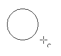
Drawing elliptical and circular arcs
|
To draw an arc, choose the appropriate Arc symbol in the Circles and Ovals toolbar. Drag with the mouse to create a guide circle or ellipse. |
|
|
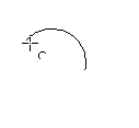
Release the mouse button and move the cursor to the position where you want the arc to start. In the status bar, you can measure the actual angle in degrees. Single-click this point; the circle (or ellipse) disappears and moving the mouse creates the arc. Again, the status bar shows the current angle. |
|
|
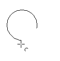
When you have drawn the arc to the length you want, click once more. The drawing of the arc is complete. |
|
The
tools for drawing curves or polygons are on the toolbar that appears
when you click the Curve
icon
![]() on the Drawing toolbar. This toolbar contains eight tools (Figure 8).
on the Drawing toolbar. This toolbar contains eight tools (Figure 8).
|
Note |
Hovering the mouse pointer over this icon gives a tooltip of Curve. If you convert the icon to a floating toolbar, however, the title is Lines, as shown in Figure 8. |
If you move the mouse cursor over one of the icons, a tooltip pops up with a description of the function. For a more detailed description of the handling of Bézier curves (curves and filled curves), see Chapter 10, Advanced Draw Techniques.
Polygons: Draw the first line from the start point with the left mouse button held down. As soon as you release the mouse button, a first corner point is drawn; move the mouse to see how subsequent lines will look. Every mouse click sets another corner point. A double-click ends the drawing. A filled polygon automatically joins the last point to the first point to close off the figure and fills it with the current standard fill color. A polygon without filling will not be closed at the end of the drawing.
Polygon 450: Like ordinary polygons, these are formed from lines but with angles of only 45 or 90 degrees between them.
Freeform Line: With this tool you can draw just like with a pencil. Press and hold the left mouse button and drag the mouse. It is not necessary to end the drawing with a double-click. Just release the mouse button and the drawing is completed. If you have selected Freeform Line, Filled, the end point is joined automatically to the start point and the object is filled with the appropriate color.
Gluepoints and connectors (basics)
All
Draw objects have associated invisible gluepoints,
which become visible when you choose any of the connectors under the
Connectors
icon
![]() on the Drawing toolbar and then move the mouse pointer over the
object.
on the Drawing toolbar and then move the mouse pointer over the
object.
Most objects have four gluepoints, as shown in Figure 10. You can add more gluepoints, and customize gluepoints, using the toolbar of the same name (Figure 11).
Gluepoints are not the same as the little blue or green “handles” of an object. The handles are for moving or changing the shape of an object, as described in Chapter 3, Working with Objects and Object Points, but the gluepoints are used to “glue” a connector to an object.
For a more detailed description of the use of gluepoints, see Chapter 9, Organization Charts, Flow Diagrams, and More.
Connectors are lines or arrows whose ends automatically dock to a gluepoint of an object. Connectors are especially useful in drawing organization charts, flow diagrams, and mind-maps. Even when objects are moved or reordered, the connectors remain attached.
Figure 12 shows two Draw objects and a connector.
Draw
offers a range of different connectors and connector functions. Open
the floating Connectors toolbar by clicking on the arrow next to the
Connector
icon
![]() (Figure 13).
(Figure 13).
For a more detailed description of the use of connectors, see Chapter 9, Organization Charts, Flow Diagrams, and More.
Geometric shapes include:
Basic shapes
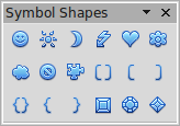
Symbol shapes
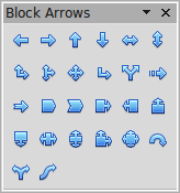
Block arrows
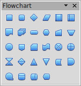
Flowcharts
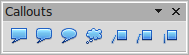
Callouts
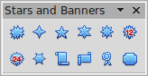
Stars
|
Note |
If you select shapes for editing, the information field in the toolbar shows the type of shape selected and, if more than one object is selected, the total number. |
Figure 14 shows part of the Drawing toolbar with the icons referred to in the following sections. Clicking on the arrow next to the icon opens a floating toolbar with the relevant work tools.
|
Tip |
The use of all these tools is similar to that of the Rectangle tool, even though they produce different geometric shapes. |
|
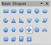
The
Basic
Shapes icon
The only differences you will see are in the information field in the status bar (in this case “Shape selected” rather than “Rectangle selected”). |
|
|
The
Symbol
Shapes icon
|
|
|
The Block
Arrows icon
|
|
|
The tools for drawing
flowcharts are accessed by clicking on the Flowcharts
icon
|
|
|
Use
the Callouts
icon
|
|
|
|
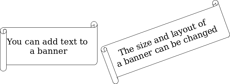
You can add text to all these shapes. See “Using text elements in Draw objects” on page 15.
Draw offers two ways to add text to a drawing: in a dynamic text frame as an independent Draw object or as text contained within a previously drawn object. In the latter case, the text is integrated with the object.
The
text tool is activated by clicking on the Text
icon
![]() for horizontal text or the Vertical
Text icon
for horizontal text or the Vertical
Text icon
![]() for vertical script (to be able see the icon and
use this latter option, you must check Enabled
for Asian languages under Tools
> Options > Language
Settings > Languages). If you still do not see
the Vertical Text icon, enable it on the Drawing toolbar by clicking
the arrow on the right hand side of the toolbar, select Visible
Buttons, and click on Vertical Text to make this icon show on the
toolbar.
for vertical script (to be able see the icon and
use this latter option, you must check Enabled
for Asian languages under Tools
> Options > Language
Settings > Languages). If you still do not see
the Vertical Text icon, enable it on the Drawing toolbar by clicking
the arrow on the right hand side of the toolbar, select Visible
Buttons, and click on Vertical Text to make this icon show on the
toolbar.
Text frames can be moved and rotated like all draw objects. For more details on text input, see Chapter 10, Advanced Draw Techniques.
After activating Text command mode, click at the location where you want to position the text. A small text frame appears. It contains only the cursor. You can move the frame, if desired. The Text Formatting toolbar appears (Figure 15), and you can choose the font type, font size, and other text properties and begin to type in your text.
The text frame grows with the text. You can insert a line break with the Shift+Enter key combination. The Enter key begins a new paragraph. Neither line breaks nor new paragraphs terminate the text frame.
Observe the information field in the status bar: it shows that you are editing text and also provides details about the current cursor location—paragraph, line, and column numbers.
Text properties can also be changed during text input. Any changes will be reflected from the cursor position onwards (Figure 17).

After choosing the Text icon, you can also draw a frame with the mouse to contain future text. You can move the frame only after typing some text in it. Line breaks are inserted automatically at the right edge of the frame when the text fills the frame width (Figure 18). You can, however,—just as when editing any other text—insert your own line breaks, begin new paragraphs, or change any of the text properties.
A text element is associated with most Draw objects. By means of these elements, text can be added to an object (see Figure 19).
The exceptions to this are control elements like buttons or list boxes, as well as 3D scenes and their associated elements and groups.
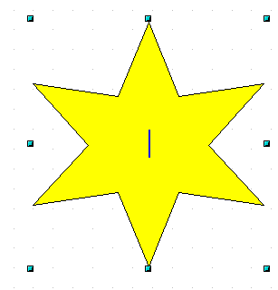
If
the Double-click
to edit Text icon
![]() on the Options toolbar is active, you can start editing an object by
double-clicking on it (or by pressing F2).
In the middle of the Draw object, a black bar indicates the text
cursor; start typing to input text. The status bar shows “Text
Edit” at the lower left and the position of the cursor within the
text.
on the Options toolbar is active, you can start editing an object by
double-clicking on it (or by pressing F2).
In the middle of the Draw object, a black bar indicates the text
cursor; start typing to input text. The status bar shows “Text
Edit” at the lower left and the position of the cursor within the
text.
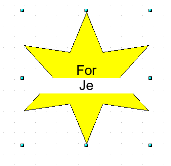
Text can contain paragraphs, and these can be in the form of bulleted or numbered lists. To begin a new line without beginning a new paragraph, use the key combination Shift+Enter (as in text documents) . To end the text input, click next to the object or press the Esc key.
|
|
|
|
|
Figure 19: Adding text to objects