Draw Guide
Chapter
3
Working with Objects and Object
Points
This document is Copyright © 2005–2011 by its contributors as listed below. You may distribute it and/or modify it under the terms of either the GNU General Public License (http://www.gnu.org/licenses/gpl.html), version 3 or later, or the Creative Commons Attribution License (http://creativecommons.org/licenses/by/3.0/), version 3.0 or later.
All trademarks within this guide belong to their legitimate owners.
Contributors
Martin Fox
Jean Hollis Weber
Feedback
Please direct any comments or suggestions about this document to: documentation@global.libreoffice.org
Acknowledgments
This chapter is based on an original French document written for OpenOffice.org 1.x by Michel Pinquier (translated into English by Alex Thurgood) and previous content revised by Jim Taylor. The chapter was revised for OpenOffice.org 2.0 by Linda Worthington, Daniel Carrera, Jean Hollis Weber, and Agnes Belzunce, and later translated into German by Wolfgang Uhlig. The German revisions were then translated into English and updated for OpenOffice 3.3 by Martin Fox. Other contributors included Hazel Russman, Gary Schnabl, and Claire Wood.
Publication date and software version
Published 13 August 2011. Based on LibreOffice 3.3.3.
Some keystrokes and menu items are different on a Mac from those used in Windows and Linux. The table below gives some common substitutions for the instructions in this chapter. For a more detailed list, see the application Help.
|
Windows/Linux |
Mac equivalent |
Effect |
|
Tools > Options menu selection |
LibreOffice > Preferences |
Access setup options |
|
Right-click |
Control+click |
Open context menu |
|
Ctrl (Control) |
z (Command) |
Used with other keys |
|
F5 |
Shift+z+F5 |
Open the Navigator |
|
F11 |
z+T |
Open Styles and Formatting window |
Contents
Moving and dynamically adjusting an object’s size 3
Dynamic size modification of objects 4
Dynamic size modification of objects with the help of the status bar 4
Rotating and shearing an object using the mouse 5
Changing inclination or perspective 6
Setting size and position exactly 7
This chapter looks at the tools and functions that let you modify existing drawings. All of the functions apply to a selected object or group of objects, which can be distinguished by small colored squares or circles located around it. These points are called handles.
The handles form a rectangular frame that is just big enough to contain the object. Where several objects are selected, the frame around them corresponds to the smallest rectangle that can contain all of the objects. This frame is called the selection rectangle.
If the Options bar is displayed (select View > Toolbars > Options to turn it on, if it is not displayed), you can change the size of the handles using two buttons: Simple Handles shows the handles as flat squares; otherwise they are shown in 3D. Large Handles increases the size of the handles. You can combine the two effects. The figure below shows the location of the handles and other buttons.
There are three selection modes:
Moving and changing size
Editing
Rotating points
To
set the default mode (1 or 2) for selecting objects, click on the
Points
button
![]() on the Drawing
toolbar.
on the Drawing
toolbar.
|
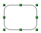
In standard mode (when you begin a new drawing), the Points button is not active, and the default mode is for selections to be moved or changed in size; these selections are indicated by small green squares. |
|
|
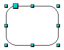
When the Points button is active, the default mode is for selections to be edited; these selections are indicated by blue squares. Some objects will have one or more extra handles, which are larger or colored differently. This is explained in more detail in “Editing object points” on page 9. |
|
|
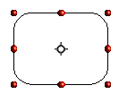
Selections
for rotating objects are indicated by small red circles and a
symbol representing the center of rotation. To choose these
selections, click on the Effects drop-down button
|
|
To go from one mode to another, you can do one of the following:
Choose the Points
button
![]() from the Drawing
toolbar to switch from simple selection mode to Points mode. You can
also use the keyboard shortcut F8
(Points). See “Editing object points” on page 9 for details on
using Points mode.
from the Drawing
toolbar to switch from simple selection mode to Points mode. You can
also use the keyboard shortcut F8
(Points). See “Editing object points” on page 9 for details on
using Points mode.
Choose the Effects
drop-down button from the Drawing
Toolbar
![]() to activate the Rotation mode for a selected object. To exit
Rotation mode, click on the Selection
icon
to activate the Rotation mode for a selected object. To exit
Rotation mode, click on the Selection
icon
![]() .
.
If you often work in Rotation
mode, you can choose the Rotation
Mode after Clicking Object button
![]() from the Options
bar and cycle through normal and rotation modes just by clicking on
the object. This can be more convenient than repeatedly clicking the
selected object, then clicking the Rotate
button from the Drawing
toolbar.
from the Options
bar and cycle through normal and rotation modes just by clicking on
the object. This can be more convenient than repeatedly clicking the
selected object, then clicking the Rotate
button from the Drawing
toolbar.
The easiest way to select an object is to click directly on it. For objects that are not filled, click on the object’s outline to select it. One click selects; a second click deselects. To select or deselect more than one object, hold the shift button down while clicking.
You can also select several
objects at once by using the mouse to drag a large rectangle around
the objects with the Select
button, as shown. For this to work, the
![]() icon on the Drawing toolbar must be active.
icon on the Drawing toolbar must be active.
Only objects that lie entirely within the rectangle will be selected.
Even if objects are located behind others and not visible, they can still be selected. Hold down the Alt key and click where the object is located. If there are several overlapping objects, hold down the Alt key and click until you reach the object you want. To cycle through the objects in reverse order, hold down the Alt+Shift keys and click. The number and type of the selected objects is shown at the left of the status bar to help you to select the correct object.
|
Note |
This method generally works in Windows, but on a Linux system it usually does not. If the Alt key on your system does not operate as described above, use the Tab key method described below. |
To select an object that is covered by another object using the keyboard, use the Tab key to cycle through the objects, stopping at the object you wish to select. To cycle through the objects in reverse order, press Shift+Tab. This is a very quick way to reach the object you want, but it may not be practical if you have a large number of objects in your drawing.
When you click on the selected object, its outline will appear briefly through the objects covering it.
|
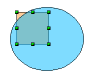
In the illustration to the right, the square located beneath the circle was selected in this way (the circle has been made semi-transparent in order to show the square). |
|
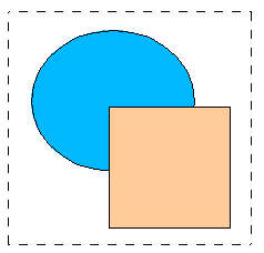
In a complex drawing, several objects may be stacked on top of one another. To rearrange the stacking order (move an object to the front or to the back of the stack), select the object, click Modify > Arrange and choose Bring Forward or Send Backward. Or right-click the object, choose Arrange from the context menu, then choose Bring Forward or Send Backward.
These
options are also available from the Arrange tear-off toolbar
accessible from the
![]() icon on the Drawing toolbar. A keyboard shortcut is Shift+Ctrl+plus
sign to bring an object to the top, and
Shift+Ctrl+minus
sign to send an object to the bottom.
icon on the Drawing toolbar. A keyboard shortcut is Shift+Ctrl+plus
sign to bring an object to the top, and
Shift+Ctrl+minus
sign to send an object to the bottom.
Note, however, that an object located on the Controls layer always lies above all other objects.
Moving and dynamically adjusting an object’s size
There are several ways of moving or changing the size of an object. The dynamic method described here uses the mouse.
When you dynamically change an object, remember to check the left-hand area of the status bar at the bottom of the Draw window. This area shows detailed information about the ongoing manipulation
For example, when you are resizing an object, the object information fields show which object is selected, the current position in X/Y coordinates, and object dimensions (width x height). The information changes as the mouse is moved. The units of measurement are those selected under Tools > Options > LibreOffice Draw > General.
|
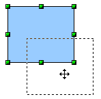
To move an object, select it and then click within the object’s border and hold down the left mouse button while dragging the mouse. During movement, the shape of the object appears as dotted lines to help with repositioning. |
|
To drop the object at its new location, release the mouse button. The new position appears immediately in the Status Bar.
Dynamic
size modification of objects
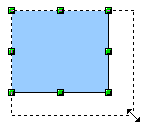
To change the size of a selected object (or a group of selected objects) with the mouse, move one of the handles located around the selection. As shown in the illustration, the outline of the resulting new object appears as a dotted line while the mouse button is pressed.
The results depend on which handle you use. To resize an object along one axis, use the appropriate side handle. To resize along both axes, use a corner handle. The new size appears immediately in the status bar.
|
Note |
If you press the Shift key while resizing an object, the change in size will be carried out symmetrically with respect to the two axes, so that the aspect ratio of the object remains the same. |
|
Caution
|
This is the default behavior of the Shift key. However, if you have used Tools > Options > LibreOffice Draw > Grid to set Snap position to When creating or moving objects, the action of the Shift key is the opposite: the aspect ratio will be preserved unless the Shift key is pressed. |
Dynamic size modification of objects with the help of the status bar
If you select an object and modify it using the mouse, the changes are immediately reflected in the information field of the status bar. With geometric shapes (such as basic shapes, symbol shapes, block arrows), the only information shown in the status bar is that the shape is being resized, as shown in the top-left image in Figure 3. With geometric elements (rectangles, circles, and so on), the changes to the attributes of the element (either relative or absolute) are also shown, as in the top-right image in Figure 3.
In the case of a rectangle, the new size is shown as percentages of the original x and y dimensions. For a line, much more information is given: the absolute change in x and y coordinates of the end point being moved, together with the current length and bearing of the modified line. These are updated dynamically as the end point is moved (see Figure 3).
This is the only place where the exact start and end angles of an arc or the length and bearing of a sloping line are shown. This information enables you to size the object with considerable accuracy.
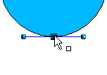
The beginning and end points of
an arc can be modified. Select the arc and click on the Points
icon
![]() on the Drawing toolbar to enter the Edit points mode (described later
in this chapter). In this mode, the handles on the selection frame
change—two
larger blue handles
appear at the beginning and end points of the arc. When the
mouse hovers over one of these points the cursor will change to a
hand.
on the Drawing toolbar to enter the Edit points mode (described later
in this chapter). In this mode, the handles on the selection frame
change—two
larger blue handles
appear at the beginning and end points of the arc. When the
mouse hovers over one of these points the cursor will change to a
hand.
If you click and hold the mouse button when the hand cursor appears, moving the mouse will change the location of the start or end point of the arc. The actual coordinates are shown in the Status Bar (see lower left graphic in Figure 3.
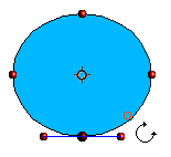
Rotating and shearing an object using the mouse
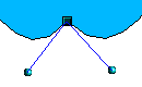
Use the red rotation handles to either rotate an object around an axis or slant or shear the object.
To rotate an object (or a group of objects), drag a red corner handle point of the selection with the mouse. The mouse cursor takes the shape of an arc of a circle with an arrow at each end. A dotted outline of the object being rotated appears and the current angle of rotation is dynamically shown in the status bar.
|
Note |
Rotation works in a slightly different way for 3D objects because the rotation occurs in 3D space and not in one plane. See Chapter 7 (Working with 3D Objects) regarding rotation when the Edit Points mode is active. |
 Rotations
are made about an axis which is displayed as a small symbol. This is
normally located at the midpoint of the object, but you can move the
axis of rotation with the mouse to any location you like, even
outside the object.
Rotations
are made about an axis which is displayed as a small symbol. This is
normally located at the midpoint of the object, but you can move the
axis of rotation with the mouse to any location you like, even
outside the object.
If you hold down the Shift key during the rotation, the operation will be carried out in increments of 15° (subject to whether Snap position is set to When creating or moving objects under Tools > Options > LibreOffice Draw > Grid).
Changing inclination or perspective
To
slant or shear objects, use the red handles located at the midpoint
of an edge of the selected objects. The mouse pointer changes to a
![]() when the pointer hovers over one of these midpoint handles.
when the pointer hovers over one of these midpoint handles.
|
Note |
In current versions of Draw, basic shapes can be sheared and slanted. The effect however will probably be different to that obtained when a classic object has the same slant or shear applied to it, particularly when the mouse is used to create the effect. |
The
slant axis is the point directly opposite the midpoint handle to be
used for shearing the object. This point stays fixed in location; the
other sides and edges move in relation to it as the mouse is dragged
(make sure that the
![]() icon is showing before dragging).
icon is showing before dragging).
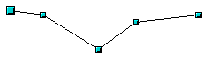
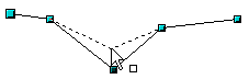
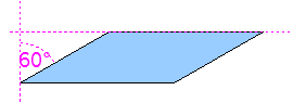
Figure 6 shows how the vertices move in relation to each other during the shearing process. The circles represent the path of the vertices. The inclination axis is the bottom vertex of the triangle (the slanting handle used is the midpoint of the upper enclosing frame). All points on the figure will move through the same angle irrespective of the final shape. The actual angle is shown in the status bar.
|
Note |
The triangle in Figure 6 was produced with the (unfilled) polygon tool and then Close Object was selected from the context menu. |
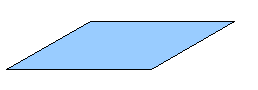
This tool can be used to produce perspective drawings. The series of pictures in Figure 7 shows the method of constructing a cuboid or rectangular prism. To shorten the edges leading from front to back, reduce the length before you distort the height or width of the surface.
As with rotation, you can make the slanting occur in steps of 15° by pressing the Shift key while moving the handle.
You can position and resize objects with the mouse, but this method is not very exact. If you need accurate positioning of objects, use Format > Position and Size from the menu bar, or right-click the object and select Position and Size from the context menu, or press F4.
Open the Position and Size dialog (see Figure 8) and click on the first tab to set the appropriate values.
Position is defined as an X,Y coordinate relative to a fixed point (the base point), typically located at the upper left of the drawing area. If desired, you can temporarily change this base point to make positioning or dimensioning simpler (click on the radio button corresponding to the location of the base point in either of the two selection windows on the right side of the dialog—upper for positioning or lower for dimensioning). The possible base point positions correspond to the handles on the selection frame plus a central point. The change in position lasts only as long as you have the dialog open; when you close this dialog, Draw resets the base point to the standard position.
|
Tip |
The Keep ratio checkbox is very useful. Click it to keep the ratio of width to height fixed while you change the size of an object. |
Either or both the size and position can be protected so that they cannot be inadvertently changed. Check the appropriate boxes to achieve this.
|
Tip |
You cannot move an object? Check to see if the position is protected! |
Click on the Rotation tab of the Position and Size dialog (see Figure 7). Here you can define the rotation angle, as well as the location of the pivot point.
The slant angle (inclination or shearing) and corner radius can be set in this dialog (Figure 10).
Corner radius
You can use this dialog to round the corners of the usual Draw objects—text boxes, legends, rectangles, and squares, as shown in Figure 11. The same effect can be achieved when you are in the points mode (click the Points icon on the Drawing toolbar), by dragging the large handle with the mouse. The larger the value for the corner radius, the rounder the object becomes.
Slant
You can shear both the older, classic Draw objects and the newer Shape objects. Enter the slant angle in the box marked Slant Angle.
|
|
|
|
|
||
For polygons and Bézier curves, Draw offers a complete set of tools that let you accurately edit the contour of an object. To edit other objects in the same way, you must first convert them into curves. To do this, select the object, then right-click and choose Convert > To Curve or choose Modify > Convert > To Curve from the menu bar.
You can also convert the shapes to a polygon (Convert > To Polygon). With polygons, the edge points are always connected with straight lines and not with curves. Some of the techniques described work equally with polygons as with curves.
Another way to change the form of basic shapes
In current versions of Draw, many of the new shapes can be directly edited without having to convert them to curves first. You can recognize these objects by the presence of one or more circular yellow handles as shown in Figure 13.
The mouse pointer changes shape when hovered over a yellow handle. If you drag one of these handles, you can modify the shape of the object; the type of change is dependent on the shape itself. For example, you can round the corners of a rectangle or square, change the angles of an arc or ellipse, or alter the control points of a circular or elliptical segment.
The editing of curves depends on the mathematics of Bézier curves1. The complete study of such curves goes beyond this scope of this guide, and only the basics are covered here. Chapter 10 (Advanced Draw Techniques) provides more information on drawing and manipulating Bézier curves.
The editing of a Bézier curve consists in principle of moving points or tangents passing through these points. Each tangent has two control points—one at each end—and a junction point where it meets the curve. The relative angle and distance between the control points determine the shape of the curve. Figure 14 shows several variations starting from a basic circle and changing only one point on the circle.
You can create many different shapes by moving either the junction point itself, or one or both of the round handle points at either end of the tangent.
Draw offers even more possibilities when you use the functions on the Bézier curve Edit Points toolbar.
When you work in Edit Points mode, use the Edit Points toolbar, shown in Figure 15. To activate this toolbar, choose View > Toolbars > Edit Points. It will then appear whenever you select a curve and the Edit Points icon on the Drawing toolbar is active.
On this toolbar, icons may be active or inactive depending on the selected object and object point. With the Convert to Curve icon, you can determine for individual points whether their connection will be made with straight lines or with curves.
Only with curves are the icons for tangents activated. An object that contains no curves is treated as a polygon.
Three buttons in the Edit Points Toolbar let you select the type of tangent and convert from one type to another. Only one of these buttons can be active at any given time. Their use is described in the following chapter.
|
|
Choose
the Symmetric
Transition button
|
|
|
Choose
the Smooth
Transition button
|
|
|
It
is also possible to separate both sides of the tangent from the
curve. In this case, the central point is known as the inflexion
point. Using this technique,
you can draw spikes and troughs in objects. Choose the Corner
Point button
|
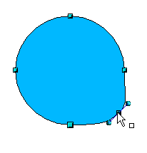
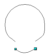
The other buttons in the Edit Points Toolbar are described here in relation to working examples. The following examples start from a filled circle. As mentioned earlier, in order to use Edit Points mode, you first need to convert the object to a curve.
You will notice that after the conversion, the handles located in the corners of the rectangle have disappeared. This behavior is normal in that the handles which are used in the Edit Points mode are located along the outline or trace of the drawn object.
|
Figure 19: Moving a
junction point |
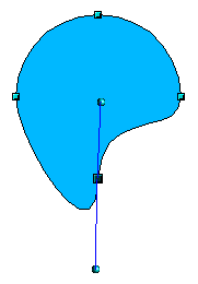
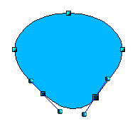
The
Move
Points button
Movement of a point is one of the easiest manipulations to do. Figure 19 illustrates how you can draw an egg very easily by starting from a circle and dragging the top point upwards. |
|||
|
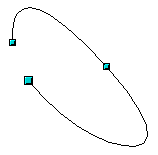
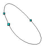
Figure 20: Rotating a
tangent |
To change the direction or location of the tangents, move the circular handles at each end. The mouse pointer then looks like this:
|
|||
|
|
Use
the
Points button
The tangent attributes associated with the new point depend on the buttons that are selected on the toolbar. |
|||
|
|
The
Delete
Points button
Select one or more points to delete. You can select several points by holding down the Shift key (➊). When
you have selected the points you want to delete, click the Delete
Points
You can also delete the selected points by pressing the Del key on the keyboard.
|
|||
|
Figure 22: Deleting
points from a curve |
||||
|
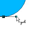
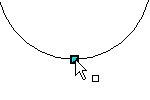
|
Use
the Split
Curve button
Check that you have selected the correct handle (➊), click the Split Curve button (➋) and notice that the object is no longer filled. You can then check, by moving the point, that the curve has indeed been separated (➌). If you have an open curve, the start point of the curve is larger than the others. |
|||
|
|
You can also separate a curve at several points simultaneously. Keep the Shift key pressed down and select all of the points at which the cut should occur. Drag and drop segments with the mouse to move them from the original curve. |
|||
|
|
To
close an existing curve, select an open curve and click on the
Close
Bézier button
The opening point is identified by a slightly larger handle (Figure 25). |
|
Select object and set
Edit points mode |
The
Eliminate
Points button
If the button is active, click on a point, hold the mouse button down and move the mouse to draw virtual straight lines between the neighboring left and right points. Release the mouse button when the two lines have more or less coalesced into one straight line. The point is deleted and the new line replaces the previous two lines, eliminating one point. Note that this only works when the angle between the two lines (shown dashed in Figure 26) is less than a certain amount. In the Tools > Options > LibreOffice Draw > Grid window there are options for snap settings relating to editing points when rotating and in point reduction mode. |
|
Draw virtual lines
|
1Bézier curves were invented by Pierre Bézier, an engineer working with the Renault car manufacturer, who developed the technique in the 1960s. The technology was intended to make modeling the surface of vehicles easier.
 Figure
18:
Figure
18: