
Impress Guide
Chapter
5
Managing Graphic Objects
Moving, rotating, distorting, and positioning objects; animations; Fontwork
This document is Copyright © 2005–2011 by its contributors as listed below. You may distribute it and/or modify it under the terms of either the GNU General Public License (http://www.gnu.org/licenses/gpl.html), version 3 or later, or the Creative Commons Attribution License (http://creativecommons.org/licenses/by/3.0/), version 3.0 or later.
All trademarks within this guide belong to their legitimate owners.
Contributors
Michele
Zarri T. Elliot Turner
Jean Hollis Weber Low
Song Chuan
Feedback
Please direct any comments or suggestions about this document to: documentation@global.libreoffice.org
Acknowledgments
This chapter is based on Chapter 5 of the OpenOffice.org 3.3 Impress Guide. The contributors to that chapter are:
Nicole
Cairns Peter Hillier-Brook Paul Miller
Hazel Russman Jean Hollis
Weber Michele Zarri
Publication date and software version
Published 31 July 2011. Based on LibreOffice 3.3.3.
Some keystrokes and menu items are different on a Mac from those used in Windows and Linux. The table below gives some common substitutions for the instructions in this chapter. For a more detailed list, see the application Help.
|
Windows/Linux |
Mac equivalent |
Effect |
|
Tools > Options menu selection |
LibreOffice > Preferences |
Access setup options |
|
Right-click |
Control+click |
Open context menu |
|
Ctrl (Control) |
z (Command) |
Used with other keys |
|
F5 |
Shift+z+F5 |
Open the Navigator |
|
F11 |
z+T |
Open Styles and Formatting window |
Contents
Set in circle (perspective) 13
Snapping objects to grid or snap guides 14
Converting an object to a different type 19
Setting up interaction with a shape 19
This chapter describes how to manage graphic objects and in particular how to rotate, distort, arrange, and position them on the slide. Though this chapter focuses on the shapes that can be created with the available tools in Impress, some of the techniques described in this chapter are also applicable to images imported into slides.
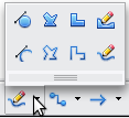
The Drawing toolbar contains the majority of the tools normally used to create graphic objects. If this toolbar is not visible, select View > Toolbars > Drawing from the main menu bar.
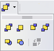
The toolbar can be divided into two parts. The first part contains drawing objects, as shown in Figure 1. The second part of the toolbar, shown in Figure 3 on page 6, contains more generic tools.
The tools in the first part of the Drawing toolbar are as follows. If you do not see a tool, go to the arrow at the end of the toolbar (shown in Figure 3), choose Visible Buttons, and then select the missing tools.
Select: selects objects. To select a group of objects, click on the top left object and, drag the mouse to the bottom right object of the intended selection while keeping the mouse button pressed. A “marching ants” rectangle identifying the selection area is displayed. It is also possible to select several objects by pressing the Shift button while selecting the individual objects.
Line: draws a straight line from the point where you click the mouse, to the point where you drag the mouse pointer and release the mouse button. Press the Shift key to restrict the angle of the line to multiples of 30°; use the Control key to detach the end point of the line from the grid (see “Snapping objects to grid or snap guides“ on page 14).
Arrow: draws a straight line ending with an arrowhead. The arrowhead is placed where you release the mouse button. The Shift and Control keys have the same effect as for the Line tool.
Rectangle: draws a rectangle when you drag the mouse from the top left to the bottom right corner. Press the Shift button to draw a square.
Ellipse: draws an ellipse. Press the Shift button to draw a circle.
Text: creates a text box with text aligned horizontally.
Vertical text: creates a text box with text aligned vertically. This tool is available only when Asian language support has been enabled in Tools > Options > Language Settings > Languages.
Curve:
draws a curve. Click the black triangle for more options (shown at
right), including polygons. Note that the title of the submenu when
undocked is Lines.
Connector:
draws a connector line between two figures. Click the black triangle
for additional connectors. Their use is described in “Working with connectors“
on page 16.
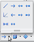
Lines
and Arrows:
draws a line ended in an arrow. Click the black triangle for
additional choices. When torn off, this toolbar is titled Arrows.
—17) Basic Shapes, Symbol Shapes, Block Arrows, Flowcharts, Callouts, Stars: click the black triangle to open a toolbar showing the available shapes in that category. The default shapes are shown in Figure 2. Select the desired shape, then draw it by dragging the mouse to define an enclosing rectangle. Keep the Shift key pressed to obtain a shape where the height and width are equal.
The tools in the second part of the Drawing toolbar are:
Edit points: to edit the individual points that form the shape or line, select this tool, and then select a shape or a line.
Glue points: to edit the glue points of a graphic object, select this tool. Glue points are the positions where connector lines terminate or start. See “Managing glue points” on page 17 for instructions.
Fontwork: opens the Fontwork gallery. See “Using Fontwork” on page 22 for further information.
From file: equivalent to Insert > Picture > From file on the main menu. See Chapter 4 for details.
Gallery: opens the gallery. Equivalent to Tools > Gallery on the main menu. See Chapter 4 for details.
Rotate: select this tool to rotate an object. As rotation is considered a formatting attribute; this is discussed in Chapter 6 of this book.
Align object: see “Aligning shapes“ on page 14.
Arrange object: see “Arranging shapes“ on page 16.
Extrusion On/Off: switches 3D effects on or off for the selected object. Clicking this button also opens the 3D settings toolbar. See “Working with 3D shapes” on page 17 for details.
Interaction: opens a dialog box where you can specify the interaction between the user and the object. See “Setting up interaction with a shape” on page 19.
Visible buttons: use the black triangle on the far right of the toolbar to open a menu from which you can add or subtract buttons on the toolbar. See Chapter 1, Introducing Impress, for more information.
Figure 4: Creating a shape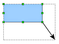
To create shapes and lines:
Select the desired line or shape tool.
Click and drag to create the object on the slide.
When drawing a freehand polygon (that is, when you create a shape segment by segment from one of the tools on the Curves toolbar, shown on page 4), keep the Shift key pressed to restrict the angle between the segments to multiples of 45 degrees. To finish drawing a polygon, double-click on the last part of the segment. If a closed polygon was selected, Impress draws the line connecting the last point to the start point and fills the inside area with the default color.
When drawing certain shapes, one or more yellow dots are displayed along with the green resizing handles. These dots perform a different function according to the shape they are applied to. With the basic shapes the yellow dot (or dots) is used for the following purposes:
Rounded rectangle and Rounded square shapes: use the yellow dot to change the size of the curve replacing the corners.
Circle Pie: use the two yellow dots to change the size of the filled sector.
Isosceles triangle: move the yellow dot on one vertex to modify the triangle type.
Trapezoid, Parallelogram, or Octagon: move the yellow dot to change the angle between the sides.
Cross: use the yellow dot to change the thickness of the four sides.
Ring: use the yellow dot to change the internal diameter.
Block arc: use the yellow dot to change both the internal diameter and the size of the filled area.
Cylinder and Cube: use the yellow dot to change the perspective.
Folded corner: use the yellow dot to change the size of the corner.
Frame: use the yellow dot to change the internal rectangle diagonal.
It is often convenient to group shapes together so that they are treated as a single shape by Impress. A group of shapes can be formatted as if it was a single shape, moved, rotated, deleted and so on. To group shapes together, do as follows:
Select the shapes to be grouped. To do this, use the selection tool on the drawing toolbar and draw a rectangle around the shapes to be grouped, or click on each shape to be added to the group while pressing the Shift key.
When the green resizing handles show, select Format > Group > Group or press Control+Shift+G on the keyboard or right-click within the group and select Group.
Once the group is defined, click on any of the shapes in the group to select the group. To edit only the shapes in the group, press F3 when the group is selected or select Format > Group > Enter Group from the menu bar or right-click and select Enter Group. Notice that any shapes not part of the group are grayed out and that only the shapes belonging to the group can be edited. Use this function when you need to apply a particular format to a single member of the group. To exit from group mode, press Control+F3 or select Format > Group > Exit group from the menu bar or right-click and choose Exit Group.
For more about working with grouped objects, see Chapter 5, Combining Multiple Objects, in the Draw Guide.
To ungroup objects:
Select the group of shapes.
When the green resizing handles show, select Format > Group > Ungroup from the menu bar or press Control+Alt+Shift+G or right-click and choose Ungroup.
|
Tip |
If you use the group and ungroup commands often, why not add them to one of the toolbars shown by default so that the commands are readily available? To do so, you will need to customize the selected toolbar. See Chapter 11, Setting Up and Customizing Impress. |
Click the graphic object, if necessary, to show the green resizing handles.
Move the pointer over the graphic object until the pointer changes shape. On most operating systems, the pointer associated with moving objects is a four-headed arrow, but it may also be a hand or some other symbol.
Click and drag the graphic object to the desired position (you can also use the arrow keys).
Release the mouse button.
|
Tip |
By default Impress makes the objects snap to the grid. If you need to position the object between two points of the grid, hold down the Control key, then click on the object and move it to the desired position. Alternatively, you can modify the grid resolution from Tools > Options > LibreOffice Impress > Grid. |
For a more accurate placement of the graphic object, use the Position and Size dialog box shown in Figure 5. First select the graphic object by clicking on it; when the resizing green handles are displayed, either press F4 or select Format > Position and Size from the menu bar.
Use the Position section of the dialog box to specify the X (horizontal) and Y (vertical) position of the graphic object. The values represent the distance of the base point (selected on the right hand side of the dialog box) relative to the top left corner of the slide.
To prevent accidental modification of the position of the graphic object, select the Position option in the Protect section (bottom left) of the dialog box.
The unit of measurement for this and the other dialog boxes in this section is set in Tools > Options > LibreOffice Impress > General.
Click the graphic object to show the green resizing handles.
Position the pointer over one of the green resizing handles. The pointer changes shape, giving a graphical representation of the direction of the resizing.
Click and drag to resize the graphic object.
Release the mouse button to complete resizing.
The corner handles resize both the width and the height of the graphic object simultaneously, while the other four handles resize only one dimension at a time.
|
Tip |
To retain the original proportions of the graphic, Shift+click one of the corner handles, then drag. Be sure to release the mouse button before releasing the Shift key. |
For more accurate resizing of the graphic object, use the Position and Size dialog box (Figure 5). Select as the base point the part of the graphic object that you would like to anchor to the page. The default setting (top left corner) means that when resizing, the position of the top left corner of the object will not change. Now modify either the Width value or the Height value of the object. To maintain the proportions between width and height, select the Keep ratio option before modifying any value. When Keep ratio is selected, changes to one of the dimension result in automatic changes to the other.
To prevent accidental modifications of the size, make sure that the Size option is selected in the Protect section in the bottom left part of the dialog box.
Besides the basic actions of moving and resizing an object, a number of special effects can also be applied to the objects in Impress. Several of these effects are readily available in the Mode toolbar. If the Mode toolbar is not showing, select it from View > Toolbars > Mode.
This section describes how to rotate, flip, distort and two ways of setting an object in a circle. The transparency and gradient tools that are more specific to formatting are discussed in Chapter 6.
Rotation of an object can be carried out manually or using a dedicated dialog box, just like changing object position and size. To rotate a graphic manually:
Select the graphic object if necessary so that the green handles show around it.
Click the Rotate
button
![]() in the Drawing toolbar or in the Mode toolbar.
in the Drawing toolbar or in the Mode toolbar.
|
Note |
The icons representing the functions in the toolbars are different depending on the operating system used and on whether LibreOffice has been customized for the Linux distribution in use or not. When in doubt, hover the mouse over the icons and wait for the tooltip to appear showing the name of the button. The tooltip for the sub-toolbar containing the Rotate function is Effects. |
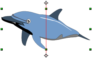
Eight red handles replace the green square handles, as shown in Figure 7. Move the mouse over one of the corner handles and the mouse cursor shape will change. Click the mouse and move in the direction in which you want to rotate the graphic object.
When satisfied release the mouse button.
At step 2) a black crosshair with a circle appears in the middle of the picture: this represents the pivot point for the rotation. Normally the center of the picture will be just fine, but on some occasions you may wish to rotate around a corner or even around a point outside the picture; to do that, click on the crosshair and drag it to the desired position.
To restrict the rotation angles to multiples of 15 degrees, press the Shift key while rotating the graphic. This is very handy for rotating pictures through a right angle, for example from portrait to landscape or back.
Instead of rotating a graphic object manually, you can use the Rotation dialog box shown in Figure 8. To display this dialog box, select the graphic object so that the green resizing handles are shown, then press F4 or select Format > Position and Size and select the Rotation page.
In the upper part of the dialog box, select the position of the pivot point relative to the top left corner of the page. The default position of the pivot point is the center of the figure.
In the lower part of the dialog box select the angle by which to rotate the graphic object. To the right of the Angle text box, 8 default rotation values can be easily selected.
Select
an object and click on the Flip
icon
![]() .
You will see a dashed line through the middle of the object.
.
You will see a dashed line through the middle of the object.
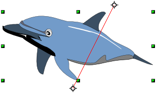
This
dashed line is the axis
of symmetry. The object will be reflected about
this line. Move one or both ends of the line with your mouse to set
the orientation of the axis.
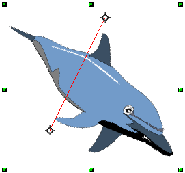
Then,
grab any one of the eight green handles and move it across to the
other side of the dashed line. The new position of the figure is
shown faintly until the mouse is released.
|
Note |
If you press the Shift key while moving the line, the line will rotate in 45-degree increments. |
This useful command does not exist in Draw or Impress. It can, however, be easily emulated.
Move the axis of symmetry to the desired location of the mirror axis. Copy the object to the clipboard. Flip the object, then click on an empty area of the page in order to deselect the object. Paste from the clipboard to put a copy of the object in its original location and now you have a mirror copy.
Three tools on the Mode toolbar let you drag the corners and edges of an object to distort the image.
The Distort tool distorts an object in perspective, the Set to Circle (slant) and Set in Circle (perspective) tools both create a pseudo three-dimensional effect. In all three cases you are initially asked if you want to transform the object to a curve. This is a necessary first step, so click Yes. Then you can move the object handles to produce the desired effect.
The results of using these tools are shown in the following figures.
Select
an object and click on the Distort
icon
![]() .
After converting to a curve as requested, move the handles to
stretch the object.
.
After converting to a curve as requested, move the handles to
stretch the object.
The corner handles distort, as shown in Figure 10. The vertical midpoint handles distort the figure horizontally and the horizontal ones distort it vertically.
Select an object and click on
the Set
in Circle (perspective)
![]() icon. After converting to a curve , move the object handles to give
a pseudo three-dimensional perspective).
icon. After converting to a curve , move the object handles to give
a pseudo three-dimensional perspective).
Select an object and click on
the Set
to Circle (slant)
![]() icon. After converting to a curve, move the object handles to give a
pseudo three-dimensional slant perspective.
icon. After converting to a curve, move the object handles to give a
pseudo three-dimensional slant perspective.
|
Note |
Transforming an object into a curve is a safe operation, but it cannot be reversed other than by clicking the Undo button. |
Use
the alignment tools to adjust the relative position of a graphic
object compared to another object. Clicking on the arrow beside the
Alignment icon in the Drawing toolbar opens the extended toolbar. The
same alignment options are available from the right-click menu.
The toolbar has six icons. The first three determine the horizontal alignment of the selected objects (Left, Center, Right); the other three determine the vertical alignment of the selected objects (Top, Middle, Bottom). If only one object is selected, it is aligned to the page; however when several objects are selected together, single objects are aligned to the group selection border.
Snapping objects to grid or snap guides
Sometimes it is important to align objects to specific points of the page or to make sure that objects that appear on multiple slides are placed in exactly the same position. For this purpose Impress provides two mechanisms: the Grid and the Snap Guides (also called Snap Lines).
Options for the grid are available in the menu that opens by right-clicking on an empty part of the page in Normal view and choosing Grid or by selecting View > Grid from the menu bar. In both cases a submenu with three options opens:
Visible Grid: displays the grid.
Snap to Grid: the anchor points of an object will always be placed on a grid when the object is moved or resized.
Grid to Front: displays the grid in the foreground.
To set up the grid spacing and snapping options, choose Tools > Options > LibreOffice Impress > Grid from the menu bar.
Options for the guides are available in the menu that opens by clicking on an empty part of the page in Normal view and choosing Snap Lines or by selecting View > Guides from the menu bar. A submenu with three options opens:
Display Guides (Snap Lines Visible): the guides are shown on the slide.
Snap to Guides (Snap to Snap Lines): the anchor points of the objects snap to the guides when the object is moved or resized.
Guides to Front (Snap Lines to Front): the guides are brought to the foreground and cover the objects.
|
Note |
The main menu uses the term Guides, but the pop-up menu refers to Snap Lines. |
To create a new guide:
Right-click on an empty part of the work area and select Insert Snap Point/Line from the pop-up menu.
In the dialog box that appears, specify the type (Point, Vertical line, or Horizontal line).
Depending on the choice made, the two edit fields X and Y become active; enter the position of the guide.
Click OK to close the dialog box.
|
Tip |
When positioning the Snap Guides, it is useful to display the rulers. To do so, select View > Rulers. |
|
Tip |
Drag a Snap Guide directly onto the slide by clicking on the ruler and then dragging onto the slide. |
To edit a guide:
Right-click next to or on the guide to be edited.
Select Edit Snap line from the pop-up menu.
Enter the new value (or values) and click OK.
To delete a guide:
Right-click next or on the guide to be deleted.
Choose Delete Snap line from the pop-up menu.
Figure 13 show the three types of guides, the grid on a slide, and the dialog box to create a new guide.
Arrange
determines the stacking order of the selected object. Draw and
Impress organize objects in a stack so that the objects on a high
level of the stack cover the objects on lower levels if overlapping
occurs. To modify the position of an object in the stack, click the
small triangle on the side of the Arrange icon to open the
extended toolbar. The same arrange options described below are
available from the right-click menu.
The first four tools determine the position of the selected object:
Bring to front: the selected object is moved on top of any other object.
Bring forward: the selected object is moved one level up in the stack.
Send backwards: the selected object is moved one level down in the stack.
Send to back: the selected object is given the lowest position in the stack.
The other three tools determine the relative positions of the selected object and of a second selected object:
In front of object: brings the first selected object in front of the second selected object.
Behind object: brings the first selected object behind the second selected object.
Reverse: swaps the stacking order of two selected objects.
To use the In front of object and Behind object tools:
Select the first object by clicking on it.
When the green handles show, select the desired arrange action.
The mouse pointer changes to a pointing hand. Click on the second object.
Connectors are lines that can be anchored to particular places, called glue points, on the graphic object. The advantage of connectors is that when the graphic object to which the connector is attached is moved or resized, the connector automatically adjusts to the change. When creating a flowchart, org chart, schematics or diagrams, it is highly recommended to use connectors instead of simple lines.
Impress offers a wide variety of predefined connectors, which differ in the termination shape (none, arrow, custom) and in the way the connector is drawn (straight, line, curved).
When a connector is drawn or selected Impress displays red handles which are not shown for normal lines; in particular, the termination points are identified by red circles, while square handles are used to modify the routing of a connector (where applicable).
Draw a connector in a similar way to drawing any object. First select the connector style from the Connector toolbar, then move the mouse cursor over one of the objects to be connected. When the cursor is over the object, small black crosses appear around it; these represent the glue points to which the connector can be attached. Click on the required glue point to attach one end of the connector, then hold the mouse button down and drag the connector to the second object. When the cursor is over the glue point of the target object release the mouse button.
For instructions on how to format a connector, refer to the corresponding section in Chapter 6, Formatting Graphic Objects.
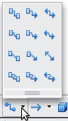
As described above, a glue point is the point of attachment for a connector to a shape or graphic object. Each shape has a number of predefined glue points, but it is possible to define new ones as well as edit them, using the Gluepoints toolbar.
Use the first tool to insert a new glue point. The next four tools determine the exit direction of the connector terminating at the glue point. To maintain the relative position of the glue point when resizing the object, make sure that the Glue point relative icon (highlighted in Figure 14) is selected. Deselecting the Glue point relative icon activates the remaining six icons on the toolbar; use these to fix the position of the glue point during the resizing of the object. Hover the mouse over the buttons to obtain a tooltip giving a short description of its function.
To delete a custom glue point, select it with the mouse and press the Delete key.
Setting custom glue points is particularly useful where multiple connectors terminate on the same side of a shape or where the default glue point position is not satisfactory.
To move a predefined or newly inserted glue point:
Select the glue point tool from the drawing toolbar (see Figure 3).
Click on the glue point you want to move. The glue point should now be highlighted.
Keep the mouse button pressed and drag the glue point to the desired position. Release the mouse button.
|
Tip |
Glue points are placed by default on the grid (see “Snapping objects to grid or snap guides“ on page 14 for information), however it is sometimes necessary to fine tune the position of the glue point depending on the shape. To do this, keep the Control key pressed while dragging the glue point to the new position. |
3D graphic objects can be created in different ways in Impress:
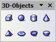
From
the 3D-Objects toolbar. The 3D-Objects tool is not included in the
default Drawing toolbar. To include it, click on the small triangle
at the end of the toolbar, select Visible
Buttons, and select 3D-Objects
from the list. On the Drawing toolbar, click on the triangle by the
3D-Objects icon to display the extended 3D Objects toolbar.
From the Convert sub-menu. Select a shape, right-click on it and in the Convert sub menu choose either To 3D to add thickness to the object or To 3D Rotation Object to create a 3D shape resulting from the rotation of the object around an axis.
From the Extrusion
on/off icon on the drawing toolbar. Select the
shape to which to apply a 3D effect, then click the
![]() button on the Drawing toolbar (see Figure 15).
button on the Drawing toolbar (see Figure 15).
|
Caution
|
You can not apply extrusion to rectangular and oval shapes created by using the rectangle or oval tools. Instead, select the desired shape from the basic shapes menu to create a rectangle or oval with 3D effects. Alternatively, right-click on the object, then select Convert > To 3D. Note that in this case the Extrusion on/off menu will not be enabled. |
Although Impress offers advanced functions to manipulate 3D objects, this book describes only the 3D settings applicable to an object with Extrusion enabled. For additional information on how to use advanced 3D effects such as geometry and shading, refer to the Draw Guide.
Click
on
![]() to activate the extrusion. The shape changes and a default thickness
is added to it. At the same time the 3D-Settings toolbar should
become visible. If the toolbar does not appear, select View
> Toolbars > 3D-Settings.
to activate the extrusion. The shape changes and a default thickness
is added to it. At the same time the 3D-Settings toolbar should
become visible. If the toolbar does not appear, select View
> Toolbars > 3D-Settings.
Use the tools to change the appearance of the 3D object.
|
|
Extrusion On/Off: adds thickness to an object and activates the 3D properties. |
|
|
Tilt Down: tilts the object downwards around an horizontal axis. |
|
|
Tilt Up: tilts the object up around an horizontal axis. |
|
|
Tilt Left: tilts the object left around a vertical axis. |
|
|
Tilt Right: tilts the object right around a vertical axis. |
|
|
Depth: determines the thickness of the shape. An extended toolbar opens where some default values are given. If none of them is satisfactory, select Custom and then enter the desired thickness. |
|
|
Direction: opens an extended toolbar that lets you pick the direction of the perspective as well as the type (parallel or perspective).. |
|
|
Lighting: opens an extended toolbar that lets you specify the direction and intensity of light. |
|
|
Surface: choose between Wire frame (useful when manipulating the object), Matt, Plastic or Metal. |
|
|
3D Color: select the color of the object thickness. |
Figure 16: Example of 3D
object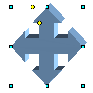
Most of the Fontwork shapes (see
“Using Fontwork” on page 22) have 3D properties and can be
manipulated with the 3D-Settings toolbar.
Note that when rotating a 3D object, in addition to the corner red handles, four handles on the sides of the frame become available.
Figure 16 is an example of a customized 3D object.
Converting an object to a different type
You can convert an object into a different type. Right-click on the object and select Convert to display a menu containing the following options:
To Curve: converts the selected object to a Bézier curve. Choose Edit Points to edit the Bézier curve.
To Polygon: converts the selected object to a polygon. After the conversion choose Edit Points to edit the shape. A polygon always consists of straight segments.
To Contour: for basic shapes, this is equivalent to converting to polygon. For more complex shapes (or for text objects) this conversion creates a group of polygons that you can then manipulate by pressing F3 to enter the group.
Convert to 3D: converts the selected object to a three-dimensional (3D) object.
Convert to 3D Rotation Object: creates a three-dimensional shape by rotating the selected object around its vertical axis.
To Bitmap: converts the selected object to a bitmap.
To metafile: converts the selected object to Windows Metafile Format (WMF), containing both bitmap and vector graphic data.
|
Note |
In most cases the conversion to a different type does not produce immediately visible results. |
Setting up interaction with a shape
You can associate a shape or an image with some action to be performed when the user clicks on it. To create an interaction:
Select the graphic object for which an interaction will be created.
When the green handles show,
select from the Drawing toolbar (Figure 3) the Interaction
button
![]() or right-click on the object and select Interaction
from the pop-up menu.
or right-click on the object and select Interaction
from the pop-up menu.
The dialog box shown in Figure 17 is displayed. Select the interaction type and the parameters (if applicable). Click OK to close the dialog box.
To remove an interaction from a graphic object follow the steps 1–5, above taking care to select No action as the interaction type at step 4.
The possible actions and their parameters are described in Table 1.
Table 1: Interactions and their parameters
|
Interaction type |
Parameters |
|
Go to Previous slide |
No parameters. |
|
Go to Next slide |
No parameters. |
|
Go to First slide |
No parameters. |
|
Go to Last slide |
No parameters. |
|
Go to Page or Object |
Specify the target from the list in the Target box. You can search for a specific target in the Document box at the bottom of the screen. |
|
Go to Document |
Select the document in the Document box. Use the Browse button to open a file picker dialog box. If the document to be opened is in Open Document Presentation format, the target list will be populated allowing the selection of the specific target in the document. |
|
Play sound |
Select the file containing the sound to be played. Use the Browse button to open a file picker dialog box. |
|
Run program |
Select the program to execute. Use the Browse button to locate it. |
|
Run Macro |
Select a macro that will run during the presentation. Use the Browse button to open the macro browser dialog box. |
|
Exit presentation |
When the mouse is clicked over the graphic object, the presentation will terminate. |
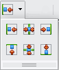
An animated image consists of a sequence of images (frames) that are displayed in succession. Each frame may contain one or multiple drawing objects. To start creating a custom animated image, open the Animation dialog box from Insert > Animated Image.
Several mechanisms can be used to create an animated image. This chapter describes only two of them, which should be sufficient to understand the functions offered.
Create the image you intend to animate using the drawing tools.
Select the image and click the
Apply
Object
![]() button. This copies the object (or objects) into the upper part of
the Animation dialog box.
button. This copies the object (or objects) into the upper part of
the Animation dialog box.
Apply some desired transformation to the object: for example, rotate it or change the color; if you are animating text, add or subtract a letter and so on.
When you are ready, create the second frame of the animation and click the Apply Object button again.
Repeat steps 3 and 4 until you have created all the desired frames of the animation.
Select Bitmap object in the Animation group section of the Animator dialog box. This allows you to customize the timing of each of the frames and the number of repetitions for the animation (set the value to Max to obtain an infinite loop).
Click Create to place the animated image on the slide.
|
Note |
If
the image to be copied in the Animator consists of several
objects, you can choose to treat each object as a separate frame.
In this case click the Apply
objects individually
button
|
For some simple animations it is possible to create all the animation frames in advance, and place them on the slide. This method works well for a rotating line, a shape gradually changing color, shapes increasing or decreasing size. In most of these occasions it is convenient to use the Edit > Duplicate command.
When
all the frames are already prepared, use the Apply
objects individually
![]() to create one frame for each of the objects.
to create one frame for each of the objects.
It is easy to obtain for example a rotating line segment:
Draw a fairly thick horizontal segment (use Format > Line or the Line and Filling toolbar to add thickness).
Open the Duplicate dialog box by selecting Edit > Duplicate and set the number of copies to 5, the X and Y axis to 0.1, the angle to 30, the enlargement width and height to 0, and press the OK button.
Select the 6 segments created by Impress and open the Animator (Insert > Animated image from the main menu bar).
On the Animator dialog box, click Apply objects individually.
Select Bitmap object in the lower part of the dialog box,
Create a new empty slide to contain your animation, then click the Create button.
Other functions of the Animator
You
can review the animation at any time by clicking the Play
button
![]() as well as navigate the various frames using the other controls
available.
as well as navigate the various frames using the other controls
available.
If you are not satisfied with a particular frame, you can remove it. To do so:
Navigate to the frame by using the Image Number box with the spin buttons (just to the right of the play controls).
Click the Delete
current image button
![]() .
.
You
can also delete the whole animation by clicking the Delete
all images button
![]() .
.
|
Tip |
If you want to work on the animation frames a bit more, you can copy them into the Impress work area by selecting Group object and then clicking Create. |
|
Tip |
Since all the objects are centered in the animation window, to animate an object off the center of the image, create a blank rectangle of the same size of the final image and select it along with the object to be animated. Make sure that Group object is selected before clicking the Apply object button. |
Use Fontwork to obtain special text effects. For more about this topic, see Chapter 11, Graphics, the Gallery, and Fontwork, in the Getting Started guide.
To start using Fontwork:
Open the Fontwork Gallery by
clicking the
![]() icon on the Drawing toolbar (see Figure 3) or on the Fontwork
toolbar (see Figure 21). If the Drawing toolbar is not showing, you
can go directly to the Fontwork toolbar by selecting View
> Toolbars > Fontwork from the main menu
bar.
icon on the Drawing toolbar (see Figure 3) or on the Fontwork
toolbar (see Figure 21). If the Drawing toolbar is not showing, you
can go directly to the Fontwork toolbar by selecting View
> Toolbars > Fontwork from the main menu
bar.
Select the preferred style from the Fontwork Gallery (Figure 19) and click OK. You can modify it later, so pick one providing an effect similar to the desired one. The text Fontwork in the selected style appears on the slide.
Double-click the object to edit the Fontwork text. Type your own text in place of the black Fontwork that appears over the object.
Press the Esc key or click outside the area with the green resizing handles to exit.
Now that the Fontwork object is created, you can edit some of its attributes. To do this, you can use the Fontwork toolbar or other options as described in the next section.
Make sure that the Fontwork toolbar, shown in Figure 21, is visible on the workspace. If not, select View > Toolbars > Fontwork from the main menu bar.
In addition to the Fontwork Gallery icon, this toolbar contains the following icons:
![]() Fontwork
shape: to change the shape of the selected object,
choose a shape from the extended toolbar.
Fontwork
shape: to change the shape of the selected object,
choose a shape from the extended toolbar.
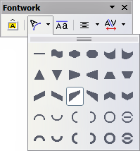
![]() Fontwork
Same Letter Heights: Changes the height of
characters in the object. Toggles between normal height (some
characters taller than others, for example capital letters, d, h, l
and others) and all letters the same height.
Fontwork
Same Letter Heights: Changes the height of
characters in the object. Toggles between normal height (some
characters taller than others, for example capital letters, d, h, l
and others) and all letters the same height.
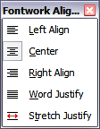
![]() Fontwork Alignment:
specify the alignment of the text within the frame from the choices
available. The effects of the text alignment can only be appreciated
if the text spans over two or more lines. In the Stretch Justify mode
all the lines are filled completely.
Fontwork Alignment:
specify the alignment of the text within the frame from the choices
available. The effects of the text alignment can only be appreciated
if the text spans over two or more lines. In the Stretch Justify mode
all the lines are filled completely.
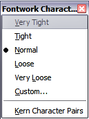
![]() Fontwork Character Spacing:
select the desired spacing and whether kerning pairs should be used.
For custom spacing, input a percentage value: 100% is normal spacing;
less than 100% is tight spacing; more than 100% is expanded spacing.
Fontwork Character Spacing:
select the desired spacing and whether kerning pairs should be used.
For custom spacing, input a percentage value: 100% is normal spacing;
less than 100% is tight spacing; more than 100% is expanded spacing.
Modifying Fontwork text as a shape
It is possible to treat Fontwork text as a shape and therefore to apply to it all the formatting that has been described in this chapter. Assign line properties only to Fontwork which does not have a 3D effect, otherwise the changes will not be visible.
|
Tip |
Change the Fontwork color quickly using the Area fill color swatch on the Line and Filling toolbar. |
You can modify some of the Fontwork shapes just as you modify the angles of Trapezoids and Parallelogram basic shapes by moving the yellow dot that is displayed along with the green resizing handles.