
Impress Guide
Chapter
6
Formatting Graphic Objects
This document is Copyright © 2007–2011 by its contributors as listed below. You may distribute it and/or modify it under the terms of either the GNU General Public License (http://www.gnu.org/licenses/gpl.html), version 3 or later, or the Creative Commons Attribution License (http://creativecommons.org/licenses/by/3.0/), version 3.0 or later.
All trademarks within this guide belong to their legitimate owners.
Contributors
Michele
Zarri
T. Elliot Turner
Jean Hollis Weber
Feedback
Please direct any comments or suggestions about this document to: documentation@global.libreoffice.org
Acknowledgments
This chapter is based on Chapter 6 of the OpenOffice.org 3.3 Impress Guide. The contributors to that chapter are:
Nicole
Cairns Peter Hillier-Brook Hazel Russman
Jean Hollis
Weber Michele Zarri
Publication date and software version
Published 31 July 2011. Based on LibreOffice 3.3.3.
Some keystrokes and menu items are different on a Mac from those used in Windows and Linux. The table below gives some common substitutions for the instructions in this chapter. For a more detailed list, see the application Help.
|
Windows/Linux |
Mac equivalent |
Effect |
|
Tools > Options menu selection |
LibreOffice > Preferences |
Access setup options |
|
Right-click |
Control+click |
Open context menu |
|
Ctrl (Control) |
z (Command) |
Used with other keys |
|
F5 |
Shift+z+F5 |
Open the Navigator |
|
F11 |
z+T |
Open Styles and Formatting window |
Contents
Fill with a line pattern (hatching) 10
Creating and importing bitmaps 18
Working with graphics styles 25
Creating a new graphic style using the Style dialog box 26
Creating a new graphics style from a selection 27
This chapter describes how to format the graphic objects created with the available drawing tools.
The format of each graphic object, in addition to its size, rotation and position on the slide, is determined by a number of attributes that define the line, text and area fill of each object. These attributes (among others) also contribute to a graphics style. Although this chapter discusses mainly the manual formatting of objects, it concludes by showing how to create, apply, modify and delete graphics styles.
In LibreOffice the term line indicates both a freestanding segment and the outer edge of a shape. In most cases the properties of the line you can modify are its style (solid, dashed, invisible, and so on), its width and its color. All these options can be applied with a few clicks of the mouse. Select the line you need to format and then use the controls on the Line and Filling toolbar to select your desired options.
If you need to fine tune the appearance of a line, choose Format > Line from the menu bar, or right-click on the line and select Line from the pop-up menu, or select the Line icon from the Line and Filling toolbar. These methods open the Line dialog box shown in Figure 2, where you can set all the properties of the line at once.
The dialog box consists of four pages: Line, Line Styles, Shadow, and Arrow Styles.
The Line page is where you can set the basic parameters of the line. It is subdivided into 4 parts.
The Line Properties section (left side) is the most important. It includes the following parameters:
Line style: a variety of line styles is available in the drop-down list, but more can be defined if needed.
Color: choose among the predefined colors or refer to “Adding custom colors” on page 12 to create a new one.
Width: specifies the thickness of the line.
Transparency: sets the transparency value of the line, a useful property when you do not want to hide the background completely. Figure 3 illustrates the effects on a line of different degrees of transparency.
The Arrow styles section of this page is only applicable to line segments; it has no effect on the line that forms the border of a shape or of a polygon. Use this section to set the styles of the two ends of the segment. You can configure the two ends independently, selecting for each of them the arrow shape (Style drop-down menu), the Width, and the termination style (Center option). Selecting the Center option moves the center of the arrowheads to the end point of the line. Figure 4 shows the effects of selecting this option. To make the two ends identical, select the Synchronize ends option. To create new arrowheads, use the Arrow styles page, as described in the following section.
The Corner style section of this page determines how the connection between two segments should look. There are four available options in the drop down menu. To appreciate the difference between corner styles, choose a thick line style and observe how the preview changes.
The bottom part of the page previews the applied style for a single line and two different corners so that the corner style choice can be quickly evaluated.
A
faster way to set the arrowheads for a selected line is to click on
the Arrow
Style
![]() icon in the Line and Filling toolbar (Figure 1).
This opens the Arrowheads menu, where you can choose one of the many
predefined arrowhead styles for the start and termination of the
selected segment.
icon in the Line and Filling toolbar (Figure 1).
This opens the Arrowheads menu, where you can choose one of the many
predefined arrowhead styles for the start and termination of the
selected segment.
Use the Line Styles page of the Line dialog box to create new line styles as well as to load previously saved line styles. Normally it is not a good practice to modify the predefined styles; instead, create new ones when necessary.
To create a new line style:
Choose Format > Line from the menu bar.
Click on the Line Styles tab.
Select from the Line style drop down menu a style similar to the desired one.
Click Add. On the pop-up dialog box, type a name for the new line style and click OK.
Now define the new style. Start by selecting the line type for the new style. To alternate two line types (for example, dashes and dots) within a single line, select different types in the two Type boxes.
Specify the number and length (not available for dot style) of each of the types of line selected, set the spacing between the various elements, and decide if the style should fit to the line width (length).
The
new line style is available only in the current document. If you want
to reuse the line style in other presentations, click the Save
Line Styles icon
![]() and type a memorable name. This saves all of the line styles in this
presentation. (Saved styles have a file extension of .sod.)
and type a memorable name. This saves all of the line styles in this
presentation. (Saved styles have a file extension of .sod.)
To make previously saved line styles available in the current presentation, click the Load Line Styles icon, select the saved list of styles, and click Open.
Use the Modify button to change the name of the style.
Use the third page of the Line dialog box to create new arrow styles such as the ones in the figure below, to modify existing arrow styles, or load previously saved arrow styles.
First draw a curve with the shape you want for the arrowhead.
|
Note |
The
arrowhead must be a curve.
A curve is something you could draw without lifting a pencil. For
example,
|
The top part of the shape will point in the direction of the line. In Figure 7 the corner at the top of the shape will point towards the “outside” of the line.
Select the curve. With the resizing handles showing, select Format > Line from the menu bar, or right-click and choose Line from the pop-up menu.
Go to the Arrow styles page (Figure 8), click the Add button, type a name for the new arrow style, and click OK.
Now you can access the new style from the Arrow style list. When you select the name of the new style, it is shown at the bottom of the dialog box.
Use the Shadow page of the Line dialog box to add and format the line shadow. The settings on this page are the same as those for shadows applied to other objects and are described in “Formatting shadows” on page 19.
A faster way to apply a shadow to the line is using the last button of the Line and Filling toolbar of Figure 1. The main disadvantage of using the toolbar button is that the shadow appearance will constrained by the shadow settings of the default graphics style.
The term area fill refers to the inside of an object, which can be a uniform color, a gradient, a hatching pattern, or an image. An area fill can be made partly or wholly transparent and can throw a shadow.
The Line and Filling toolbar has the majority of the tools normally used to format graphic objects. If this toolbar is not showing, choose View > Toolbars >Line and Filling from the menu bar. You can also use the Area dialog box, described on page 10.
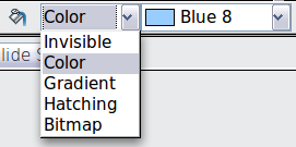
To format the area of an object, select it so that the green resizing handles show. A wide number of default fillings are readily available from the Line and Filling toolbar. Select first from the pull-down menu to the right of the paint can icon the type of fill. If you want no fill at all, select Invisible.
Once you have decided on a predefined or custom fill, you can further refine it by adding a shadow or transparency.
Select the object you wish to edit. On the Line and Filling toolbar, select Color on the pull down list at the right of the paint can, and then choose a color from the drop-down menu.
A gradient fill provides a smooth transition from one color to another. The transition pattern may vary from a simple linear transition to a more complex radial transition.
Select the object you wish to edit. On the Line and Filling toolbar, select Gradient and then choose a gradient from the drop-down menu.
Fill with a line pattern (hatching)
Select the object you wish to edit. On the Line and Filling toolbar, select Hatching and then choose a hatching fill from the drop-down menu. A hatching fill is applied throughout the area.
You can fill an object only with a bitmap image (as opposed to a vector graphic image). Select the object you wish to edit. On the Line and Filling toolbar, select Bitmap and then choose a bitmap fill from the drop-down menu.
In addition to using the Line and Filling toolbar, you can use the Area dialog box to apply existing fills and create your own. To open it, choose Format > Area from the menu bar, or click on the paint bucket icon on the Line and Filling toolbar, or right-click on the object and select Area.
Use the Area tab to apply predefined fills, both those supplied with LibreOffice and those you create yourself. Use the Colors, Gradients, Hatching, and Bitmaps tabs to define new fills, as described in “Creating new area fills” on page 12. The Transparency tab is discussed on page 20. To make the object cast a shadow, see page 19.
To apply an area fill, first select in the top left drop-down list the required fill type. The page changes to show in the middle section the list of predefined styles for that fill type.
|
Note |
In the Area dialog box, the choice for no fill is None rather than Invisible. |
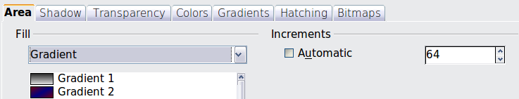
When using the Area tab of the Area dialog box, some additional options may become available once you have selected the fill type and one of the available fill styles.
For gradient fills, you can override the number of steps (increments) that should be applied to the transition from one color to the other. To do so, select Gradient on the Area tab and deselect the Automatic option under Increments. Then enter the number of steps required in the box to the right.
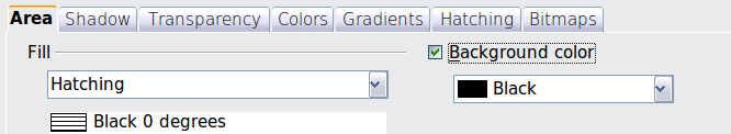
For hatching, you can apply a different background color by selecting the Background color option and choosing a color from the drop down list.
For bitmaps, you can customize a large number of parameters. Refer to “Working with bitmap fills” on page 16 for additional information.
The following sections describe how to create new fills and how to apply them.
Although you can change the characteristics of an existing fill and then click the Modify button, it is recommended that you create new fills or modify custom fills rather than the predefined ones, as these may be reset when updating LibreOffice.
On the Colors page, shown in Figure 16, you can modify existing colors or create your own.
You can specify a new color either as a combination of the three primary colors Red, Green, and Blue, (RGB notation) or by the percentage of Cyan, Magenta, Yellow, and Black (CMYK notation).
To create a new color:
Enter the name for the color in the Name box.
Select whether to define the color in RGB or CMYK. For RGB Specify the red, green and blue component on a 0 to 255 scale. For CMYK specify the Cyan, Magenta, Yellow and black (K) components, from 0% to 100%.
Click the Add button. The color is now added to the list on the Area page.
To modify a color:
Select the color to modify from the list.
Enter the new values that define the color (if necessary change the settings between RGB and CMYK).
Modify the name as required.
Click the Modify button.
Alternatively, use the Edit button (this will open a new dialog box), modify the color components as required and click OK to exit the dialog box.
Use the Load and Save buttons in the dialog to use a different color palette or to save your own custom colors.
|
Tip |
You can also add custom colors using Tools > Options > LibreOffice > Colors. This method makes the color available to all components of LibreOffice, whereas colors created using Format > Area > Colors are only available for Impress. |
To create a new gradient or to modify an existing one, select the Gradients tab from the Area dialog box. Several types of gradients are predefined and in most cases changing the From and To colors will be sufficient to obtain the desired result.
It is highly recommended that you create a new gradient even if you just want to change the two colors, rather than modifying the predefined ones, which should be used only as starting points.
To create a new gradient:
First choose the From and To colors.
Then choose a type of gradient from the list: Linear, Axial, Radial, Ellipsoid, Square or Rectangular.
A preview of the gradient type is shown under the available gradients list in the middle of the dialog box. Figure 17 shows an example.
Depending on the chosen type some options will be grayed out. Set all the properties as desired (very often the default values will work well). The properties to set to create a gradient are summarized in Table 1.
Click the Add button to add the newly created gradient to the list.
|
Tip |
The newly created gradients remain available to all the LibreOffice components and also for future presentations. It pays to give them memorable names. |
Table 1: Gradient properties
|
Property |
Meaning |
|
Center X |
For Radial, Ellipsoid, Square and Rectangular gradients, modify these values to set the horizontal offset of the gradient center. |
|
Center Y |
For Radial, Ellipsoid, Square and Rectangular gradients, modify these values to set the vertical offset of the gradient center. |
|
Angle |
For all the gradient types, specifies the angle of the gradient axis. |
|
Border |
Increase this value to make the gradient start further away from the border of the shape. |
|
From |
The start color for the gradient. In the edit box below enter the intensity of the color: 0% corresponds to black, 100% to the full color. |
|
To |
The end color for the gradient. In the edit box below enter the intensity of the color: 0% corresponds to black, 100% to the full color. |
You can create new hatching patterns or modify existing ones. Start by selecting the Hatching tab of the Area dialog box.
As with gradients and colors, it is better to create a new pattern rather than to modify a predefined one.
To do so:
Select as a starting point a pattern similar to the one that will be created..
Modify the properties of the lines forming the pattern. A preview is displayed in the window below the available patterns.
Click the Add button and choose a name for the newly created hatching.
The properties that can be set for a hatching pattern are shown in Table 2.
Table 2: Properties of hatching patterns
|
Property |
Meaning |
|
Spacing |
Determines the spacing between two lines of the pattern. As the value is changed the preview window is updated. |
|
Angle |
Use the mini map below the numerical value to quickly set the angle formed by the line to multiples of 45 degrees. If the required angle is not a multiple of 45 degrees, just enter the desired value in the edit box. |
|
Line type |
Set single, double or triple line for the style of the pattern. |
|
Line color |
Use the list to select the color of the lines that will form the pattern. |
On the Area tab, chose Bitmap from the drop down list. Select from the list of bitmaps the one to be used to fill the area. Note that any imported bitmaps will become available in the list.
Set the size, position and offset parameters (as applicable) in the right hand side of the page, and then click OK to close the dialog box.
As Figure 21 shows, there are quite a number of parameters to be configured when using a bitmap fill. These are described in Table 3.
Table 3: Bitmap fill properties
|
Property |
Meaning |
|
Size – Original |
Select this box to retain the original size of the bitmap. |
|
Size – Relative |
To rescale the object, deselect the Original option and select this one. The Width and Height edit boxes are enabled. |
|
Size – Width |
When Relative is selected 100% means that the bitmap original width will be resized to occupy the whole fill area width, 50% means that the width of the bitmap will be half that of the fill area. |
|
Size – Height |
When Relative is selected 100% means that the bitmap original height will be resized to occupy the whole fill area height, 50% means that the height of the bitmap will be half that of the fill area. |
|
Position – Anchor Map |
Select from the map the place within the area to which the bitmap should be anchored. |
|
Position – Tile |
When this option is selected, the bitmap will be tiled to fill the area. The size of the bitmap used for the tiling is determined by the Size settings. |
|
Position – X offset |
When Tile is enabled, enter in this box the offset for the width of the bitmap in percentage values. 50% offset means that Impress will place the middle part of the bitmap at the anchor point and start tiling from there. |
|
Position – Y offset |
This will have a similar effect to the X offset, but will work on the height of the bitmap. |
|
Position – Autofit |
Stretches the bitmap to fill the whole area. Selecting this option disables all the size settings. |
|
Offset – Row |
If Tile is enabled, offsets the rows of tiled bitmaps by the percentage entered in the box so that two subsequent rows are not aligned. |
|
Offset – Column |
If Tile is enabled, offsets the columns of tiled bitmaps by the percentage entered in the box so that two subsequent columns of bitmaps are not aligned. |
The best way to acquire understanding of these parameters is to use them. Figure 22 shows some examples of bitmap fills and the parameters used.
Creating and importing bitmaps
You can add (import) new bitmap fills or create your own pattern on a 8x8 grid, using the Bitmaps tab of the Area dialog box (shown in Figure 23).
To create a bitmap fill:
Start with the Blank bitmap type on top of the list to activate the Pattern editor.
Select the Foreground and Background colors.
Start creating the pattern by clicking with the left mouse button the squares (pixels) that you want to be painted in the foreground color. Use the right mouse button to apply the background color. Check the preview window to see if the desired effect is achieved.
When done, click Add to save the pattern.
To import a bitmap created in Draw or another program:
Click the Import button.
A file picker dialog box is displayed. Browse to the directory containing the bitmap file and select it, then click Open.
Type a name for the imported bitmap and click OK.
|
Note |
Bitmaps generally have an extension .bmp or .png. To create a bitmap image with Draw, select File > Export, choose PNG from the pull-down list of file formats, give the file a name, and save it. |
Shadowing can be applied to both lines and areas. To apply a shadow to an area, first select the object to which shadowing should be applied, then select Format > Area.
Shadows
can also be applied to lines. One way is to click the Shadow
icon
![]() on the Line and Filling toolbar (the last tool on the right-hand
end). The other way is to apply a style to the line that uses a
shadow (see “Working with graphics styles” on page 25 for
additional information on using styles).
on the Line and Filling toolbar (the last tool on the right-hand
end). The other way is to apply a style to the line that uses a
shadow (see “Working with graphics styles” on page 25 for
additional information on using styles).
Using the first method, you cannot customize the shadow; it is applied according to the default settings. The second method offers the opportunity to configure the shadow properties.
The dialog box to customize a shadow is shown in Figure 24.
When the Use shadow option is selected, the following parameters can be set:
Position: the selected point in the mini map determines the direction in which the shadow is cast.
Distance: determines the distance between the object and the shadow.
Color: sets the color of the shadow.
Transparency: determines the amount of transparency for the shadow.
|
Tip |
When the transparency value is set above 0%, the shadow does not completely hide the objects below. This produces a pleasant visual effect, as shown in Figure 25. |
Transparency is applicable to lines and areas as well as shadows. To apply transparency to lines, refer to “Formatting lines” on page 4; for shadows, refer to “Formatting shadows” above.
To apply transparency to areas, select Format > Area and then go to the Transparency page shown in Figure 26.
The two types of transparency are uniform transparency and gradient transparency. To obtain uniform transparency, select Transparency and then select the percentage of transparency required. For a gradient transparency (so that the area becomes gradually transparent) select Gradient and then set the parameters of the gradient. Refer to Table 1 on page 14 for a description of most of the settings. In the Transparency tab, specify the Start value and the End value for the transparency gradient. 0% is fully opaque, 100% means fully transparent.
An example of gradient transparency is shown in Figure 27.
More information on gradient transparency, including an example of combining color gradient with gradient transparency, can be found in “Advanced gradient controls” on page 21.
As discussed in “Creating gradients” on page 13 and “Transparency formatting” on page 20, gradient properties can be configured using the parameters in Table 1 on page 14.
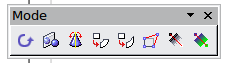
Impress
also provides a graphical interface for modifying the gradient
parameters using only the mouse. To use these tools, click on the
Transparency
icon
![]() or the Gradient
icon
or the Gradient
icon
![]() in the Mode toolbar.
in the Mode toolbar.
When an object with a gradient fill is selected, click on the Gradient icon to display a dashed line connecting two squares colored as the “From” color and the “To” color of the gradient, as shown in the examples below.
For linear gradients, move the square corresponding to the From color to change where the gradient starts (that is the Border property). Move the square corresponding to the To color to change the orientation (Angle property).
For axial gradients, you can move only the To color to change both the angle and the border properties of the gradient.
For radial gradients, move the From color to modify the border property (that is how “wide” the gradient circle is). Move the To color to change the point where the gradient ends (Center X and Center Y values).
For ellipsoid gradients, move the From color to modify the border property (the size of the gradient ellipsoid). Move the To color to change the angle of the ellipsoid axis and the axis itself.
For square and rectangular gradients, move the From color to modify the border (the size of the gradient square or rectangle) and the angle of the gradient shape. Move the To color to change the center of the gradient.
The same actions can be performed for transparency gradients, with the difference that the two squares activated by the Transparency icon represent the fully opaque point (black square) and the fully transparent point (white square).
These icons are grayed out by default and are only activated when an object with gradient filling, gradient transparency, or both is selected.
In both cases a dashed line connecting two small squares appears on top of the object. Click outside the object to set the gradient.
|
Note |
Moving the squares will have different effects depending on the type of gradient. For example, for a linear gradient, the start and end squares of the gradient will always be situated to either side of the center point of the object. |
Impress provides two dialog boxes related to text formatting: Format > Character and Format > Text.
To modify formatting such as font and font effects, select the text in the shape and then go to Format > Character. For more information, see Chapter 3, Adding and Formatting Text. This section covers the formatting of the overall shape of text which is added to a line or to a shape.
To add text to an object (a shape or a line):
Select the object to which text will be added.
With the green resizing handles showing, double-click on the object and wait for the cursor to become an I-beam or just start typing.
Type the text. When finished, click somewhere outside the object or press Esc.
To format the text in a shape:
Select the object to which text was added.
Select Format > Text or right-click on the shape and select Text from the pop-up menu. The Text dialog box is displayed.
The top section of the page (Text) offers several options in the form of checkboxes. Some of the options will be grayed out, depending on the object to which the text will be attached.
Select Fit width to text to expand the width of the shape or line if the text is too long for it.
Select Word wrap text in shape to start a new line automatically when the edge of the shape is reached.
Select Fit height to text to expand the object height whenever it is smaller than the text (set by default for lines).
Select Resize shape to fit text to expand a custom shape when the text inserted in the shape is too large.
Select Fit to frame to expand the text so that it fills all the available space.
Select Adjust to contour to make the text follow a curved line.
In the Spacing to borders section, specify the amount of space to be left between the border of the shape or line and the text; this is similar to the settings for indentation and spacing for paragraphs.
The text anchor grid in the bottom right corner of the dialog box is used to decide where to anchor the text. The Full width option determines if the anchoring should be performed to the full width of the shape.
Use the Text Animation page to add special effects to the text. Choose between the four options on the list and when applicable, the direction of the effect by picking one of the four arrow buttons to the right. The available effects are:
Blink: the text will blink on the screen.
Scroll through: the text will move into the shape and then out following the chosen direction.
Scroll back and forth: the text will move first in the chosen direction but will bounce back at the shape border.
Scroll in: the text will scroll in towards the given direction starting from the edge of the shape and stop in the center.
The default is no animation.
The other properties that can be set are:
Start inside option: when set the animation will start from inside the shape.
Text visible when editing option: set this box to see the text while editing.
Animation cycles: includes three further options to set the frequency of the animation, the increments between two positions of the animation and finally the delay before the animation starts.
To see some of the animations in action, it is necessary to start the presentation. Press F9 or select Slide Show > Slide Show from the main menu. To return to the edit mode, press Esc.
Connectors are lines that join two shapes. Connectors always start from a glue point on the shape. Refer to Chapter 5, Managing Graphic Objects, for a description of the use of connectors.
Connector properties can be accessed and modified in two ways:
Manual formatting: right-click on the connector line and select Connector in the pop up menu.
Style-based formatting: select one of the available graphics styles or create a new one.
Both methods open the Connector dialog box where you can set the style of the connectors. Choose between Standard (the default), Line, Straight, and Curved connector. Whenever multiple connectors overlap, use the Line skew section of the dialog box to distance the lines. It is possible to customize the distance between 4 different lines.
In the Line spacing section of the dialog box, set the horizontal and vertical space between the connector and the object at each end of the connector.
To achieve consistency in the style across the slides of a presentation (or a presentations portfolio), or simply to apply the same formatting to a large number of objects, the best approach is to use graphics styles.
Graphics styles are the equivalent for graphic objects of paragraph styles for text. A graphics style groups all the formatting attributes that a graphic object can have and associates this with a name, making them quickly reusable. If a style is modified (for example, by changing the area transparency), the changes are automatically applied to all the graphics with that style.
If you use Impress frequently, a library of well-defined graphics styles is an invaluable tool for speeding up the process of formatting your work according to your taste or any style guidelines you may need to follow (company colors, fonts and so on).
Use the Styles and Formatting window to access styles you will need often. If the window is not visible, press F11, or click the Styles and Formatting icon at the left-hand end of the formatting bar, or select Format > Styles and Formatting from the menu bar. Press F11 again when the dialog box is not needed, to maximize the workspace area.
Graphic styles support inheritance; that is, a style can be linked to another (parent) style so that it inherits all the formatting settings of the parent. You can use this property to create “families” of styles.
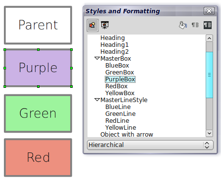
For example, if you need multiple boxes that differ in color but are otherwise identically formatted, the best way to proceed is to define a generic style for the box including borders, area fill, font, and so on and a number of hierarchically dependent styles which differ only in the fill color attribute. If later you need to change the font size or the thickness of the border, it is sufficient to change the parent style and all the other styles will change accordingly.
You can create a new graphics style in two ways:
Using the Style dialog box
From a selection
Creating a new graphic style using the Style dialog box
Choose
the Graphics Styles icon
![]() at the top of the Styles and Formatting window.
at the top of the Styles and Formatting window.
To link a new style with an existing style, first select that style, and then right-click and choose New. Otherwise, select Default, then right-click and choose New.
As discussed in the preceding section, when styles are linked, changing the font will change it in all the linked styles. Sometimes this is exactly what you want; at other times you do not want the changes to apply to all the linked styles. It pays to plan ahead.
The Graphics style dialog box consists of 14 pages (15 if Asian language support has not been enabled) that may be grouped as follows:
The Organizer page contains a summary of the style and its hierarchical position.
The Font, Font Effects, Indents & Spacing, Alignment, Tabs and Asian typography pages set the properties of the text inserted in a text box or in an graphic object.
The Dimensioning page is used to set the style of dimension lines.
The Text, Text animation, Connector, Line, Area, Shadowing, and Transparency pages determine the formatting of a graphic object and are discussed elsewhere in this chapter.
|
Note |
In most cases you will not need to configure the parameters of every page; for example, to create a simple line style you will probably only use 3 of the 15 pages. |
Creating a new graphics style from a selection
You can create a new style from manually formatted text or graphics:
Select the item you want to save as a style. If the selected object is already styled, then the new style will be linked to such style.
In the Styles and Formatting window, click the New Style from Selection icon, highlighted in Figure 34.
In the Create Style dialog box that pops up, type a name for the new style. The list shows the names of existing custom styles of the selected type. Click OK to save the new style.
To change an existing style, right-click on it in the Styles and Formatting window and choose Modify from the pop-up menu.
The dialog box for the modification of a graphic style is the same as the one for creating a new graphic style.
Make the required changes to the style and then click OK to save them.
Updating a graphics style from a selection
To update a style from a selection:
Select an item that has the format you want to adopt as a style.
In the Styles and Formatting window, select the style you want to update, and then click the Update Style icon.
|
Tip |
Any changes you make to a style are effective only in the document on which you are working. The changes do not go into any associated template. If you want the changes to apply to more than one document, you need to change the template (see Chapter 2). |
You can apply a graphics style in two ways, both starting from the Styles and Formatting window. First make sure that the graphic styles are shown, then do one of the following:
Select the object to which you want to apply a graphic style and double-click on the name of the style you want to apply.
Click the Fill
Format mode icon
![]() .
The mouse pointer changes to this icon. Position the moving icon on
the graphic object to be styled and click the mouse button. This
mode remains active until you turn it off, so you can apply the same
style to several objects. To quit Fill Format mode, click the Fill
Format mode icon again or press the Esc
key.
.
The mouse pointer changes to this icon. Position the moving icon on
the graphic object to be styled and click the mouse button. This
mode remains active until you turn it off, so you can apply the same
style to several objects. To quit Fill Format mode, click the Fill
Format mode icon again or press the Esc
key.
When Fill Format mode is active, a right-click anywhere in the document undoes the last Fill Format action. Be careful not to accidentally right-click and thus undo actions you want to keep.
|
Tip |
At the bottom of the Styles and Formatting window is a drop-down list. You can choose to show all styles or groups of styles such as applied styles or (in the case of graphics styles) custom styles. |
You cannot delete any of the predefined styles, even if you are not using them.
You can delete any user-defined (custom) styles, but before you do, you should make sure the styles are not in use. If an unwanted style is in use, replace it with a substitute style.
To delete unwanted styles, right-click on them (one at a time) in the Styles and Formatting window and click Delete on the pop-up menu. Click Yes in the message box that pops up.
Assigning styles to shortcut keys
LibreOffice provides a set of predefined keyboard shortcuts which allow you to quickly apply styles while typing in a document. You can redefine these shortcuts or define your own, as described in Appendix A, Keyboard Shortcuts.
 is a curve but
 is not a curve. You can however
draw shapes which are not curves and then at the end convert them
to a curve.
is not a curve. You can however
draw shapes which are not curves and then at the end convert them
to a curve.